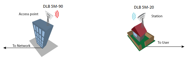
Perform the following steps to create a simple Point-to-Point link between Access Point iPoll 2 and Station (WDS/iPoll 2):
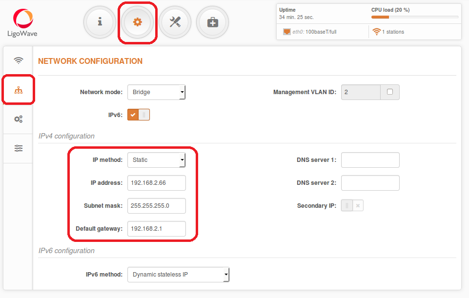
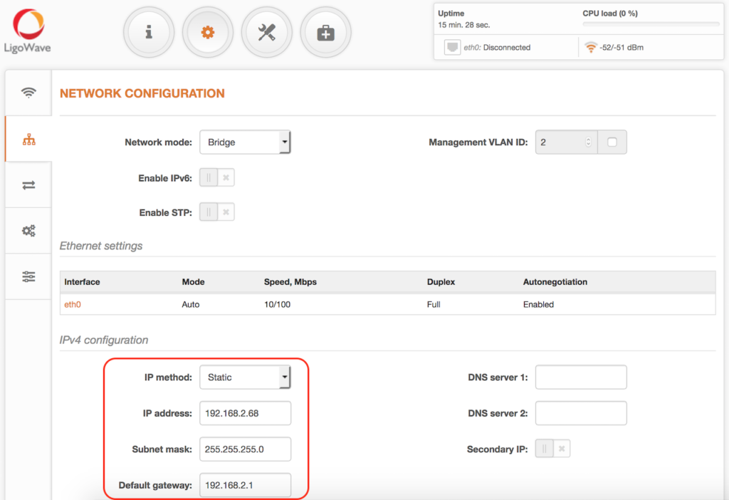
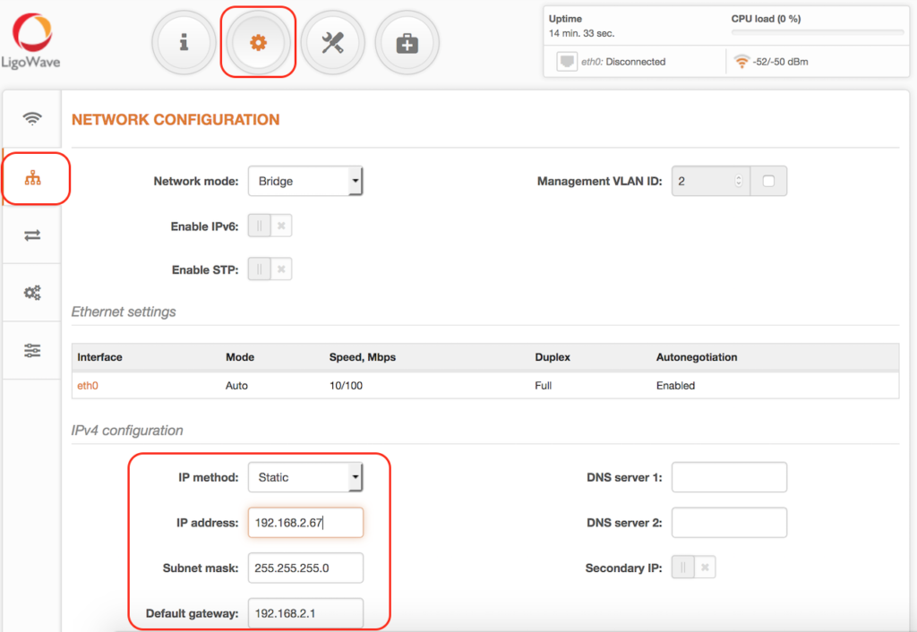
Step 1. Access Point iPoll 2 Configuration. Change the device’s default IP address (can be static or dynamic) and enable IP alias (secondary IP), if necessary:
Step 2. Configure the wireless settings for Access Point iPoll 2:
- set Wireless mode to Access Point (iPoll 2);
- set Channel to Auto;
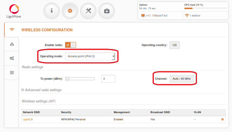

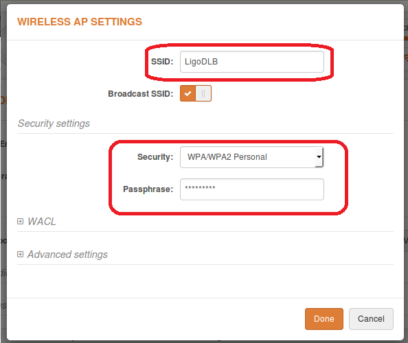
- set the SSID;
- enable Security for secure traffic on link.
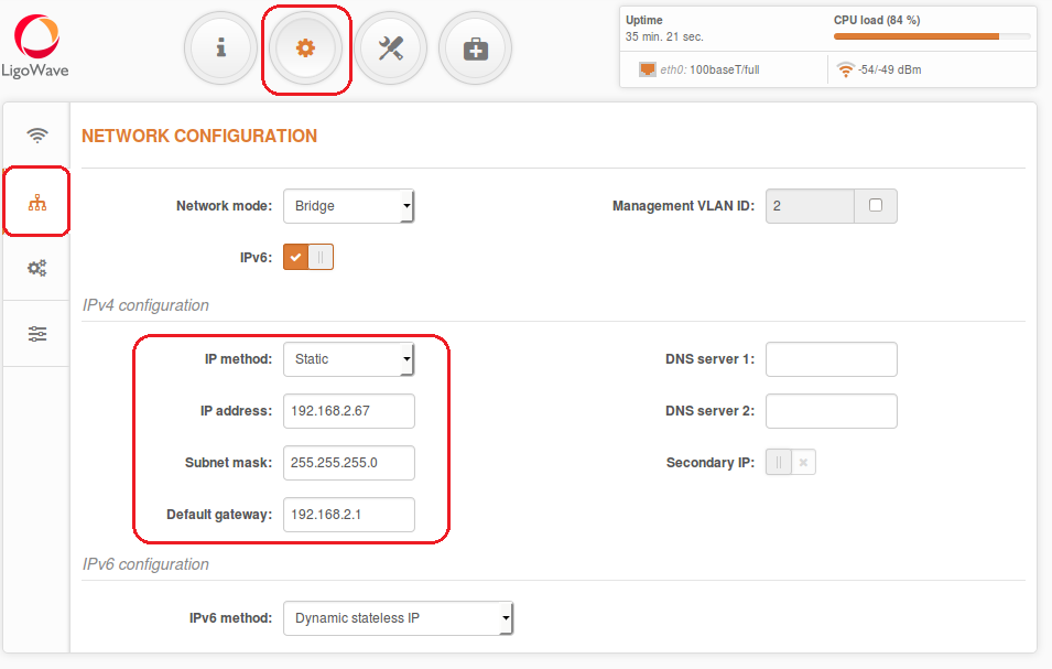
Step 3. Station iPoll 2 Configuration. Change the device’s default IP address (can be static or dynamic) and enable IP alias (secondary IP), if necessary:
Step 4. Configure the wireless settings for Station iPoll:
- set Wireless mode to Station (WDS/iPoll 2).
All other settings should be left as their default values.
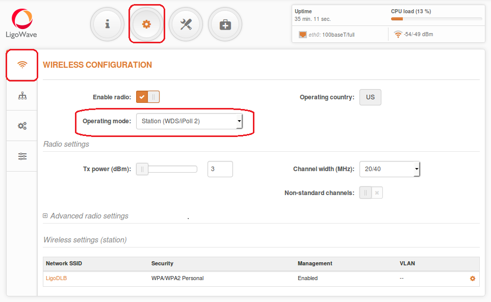

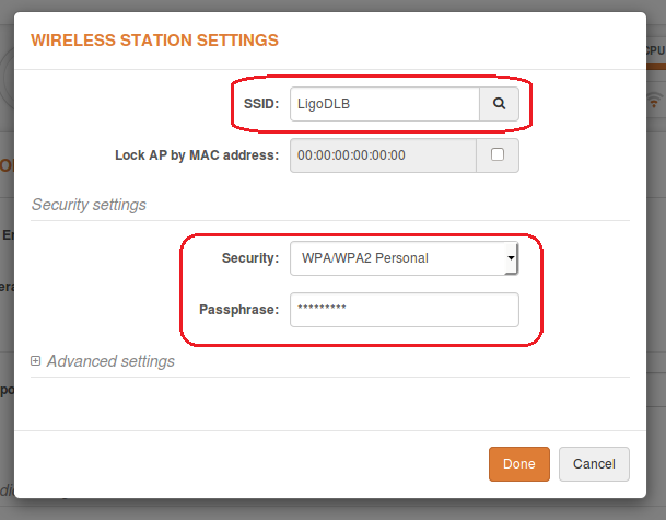
- set the SSID or use Scan to find iPoll 2 Access Points automatically;
- enable Security for secure traffic on link.
All other settings should be left as their default values.
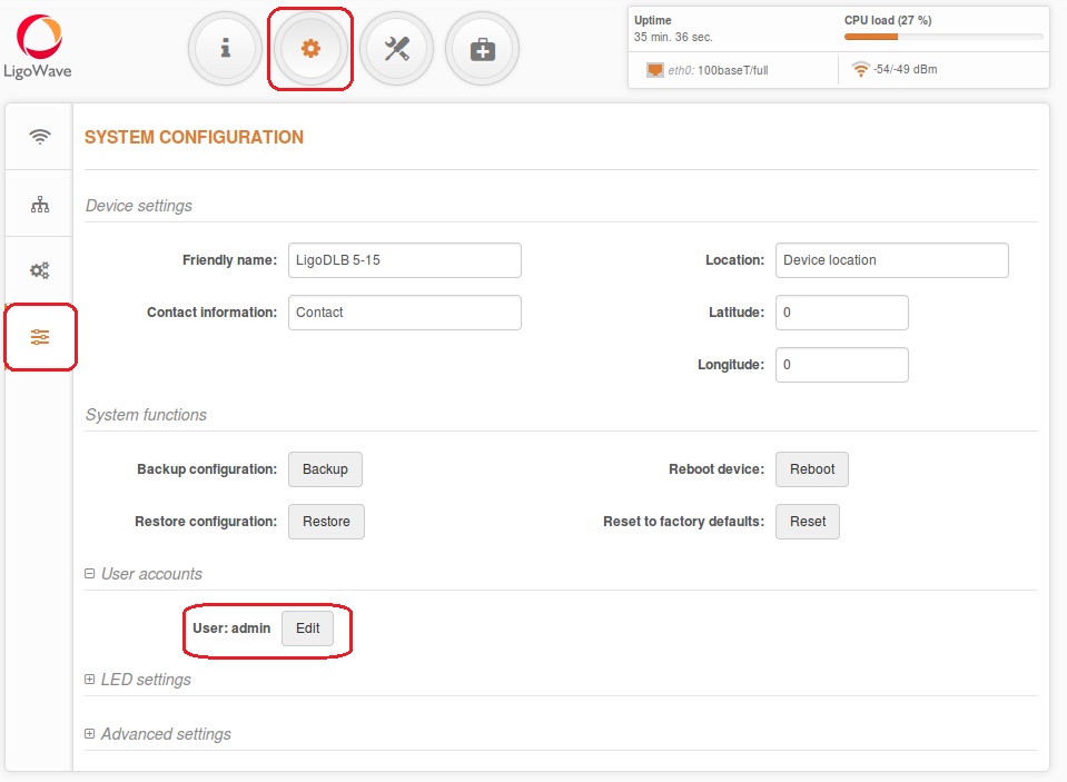
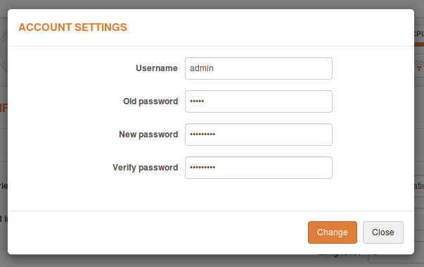
Step 5. It is highly recommended to change the default administrator’s password for each unit:
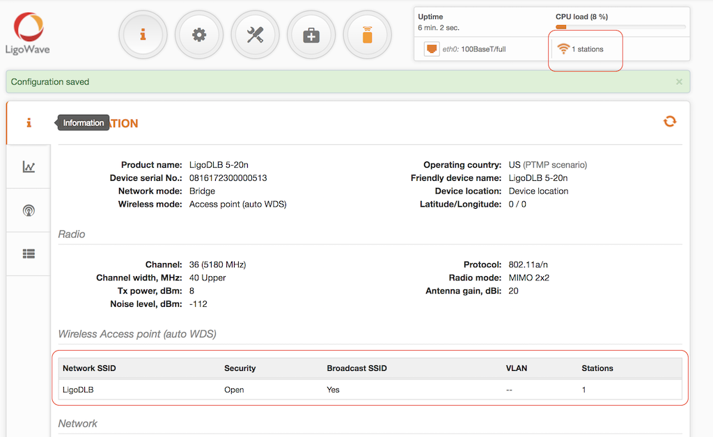
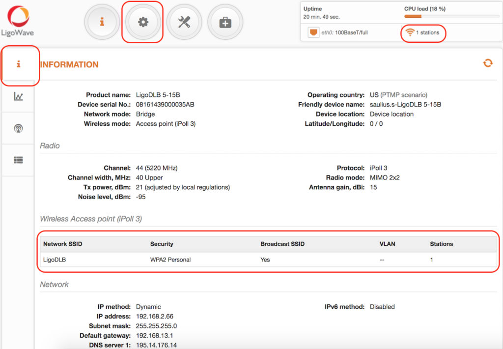
Access Point iPoll 2’s status page should indicate that one peer (Station iPoll 2) is connected and should provide information about the connection as follows:
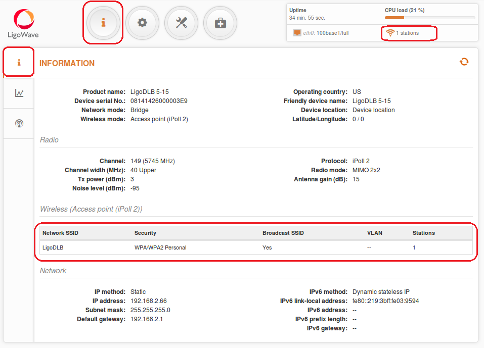
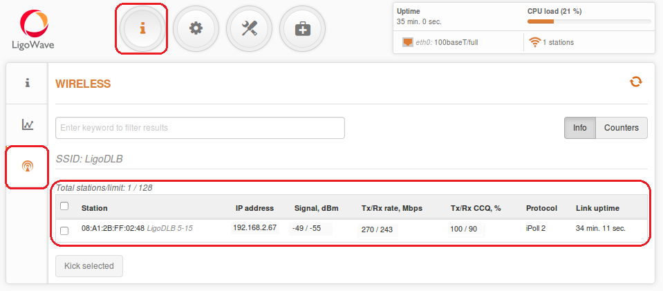
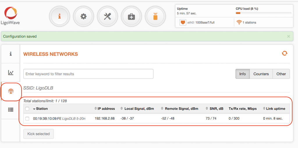
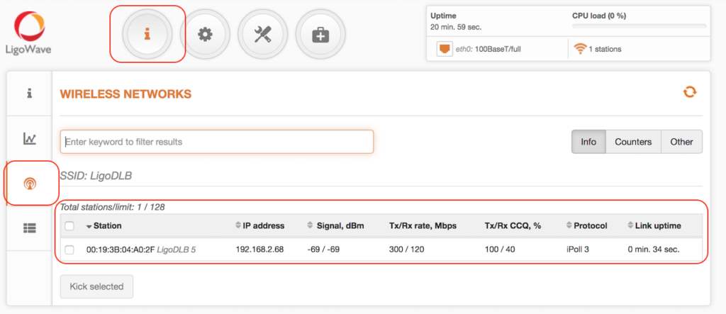
Detailed information about the connected peers is found in the Status > Wireless page.
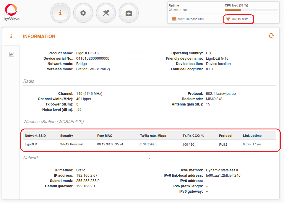
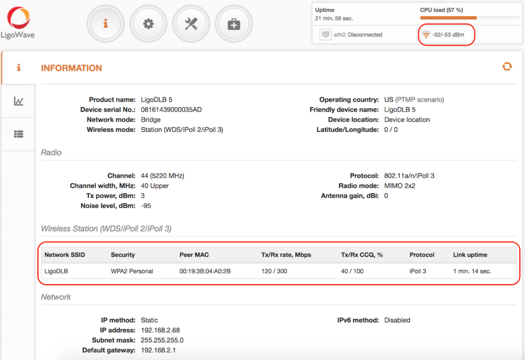
Station iPoll 2’s status should show up as Connected and there should be progress bars indicating the quality of the connection:
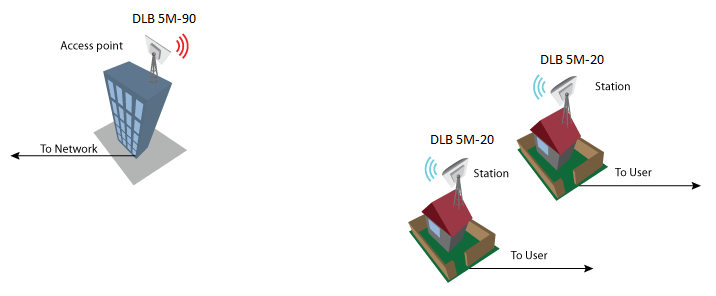
Configuration of a Point-to-Multipoint (Auto WDS) Bridged Network
Configuration of WDS Mode
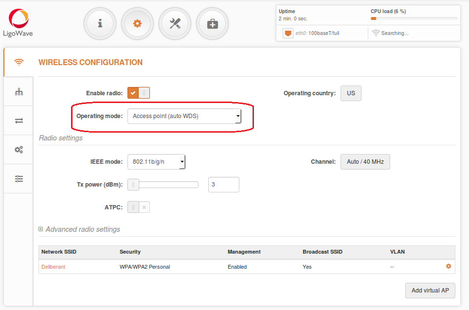
Steps for configuring the wireless settings for an 11n AP:
- set Wireless mode to Access Point (auto WDS);
- choose IEEE mode: use N, if 802.11n-capable radios are used; use A/N mixed or B/G/N mixed, if legacy radios are used on the network;
- set Channel to Auto;
- set ACK timeout based on the maximum distance from the station.
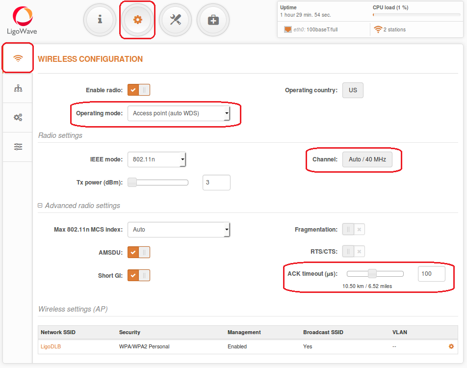
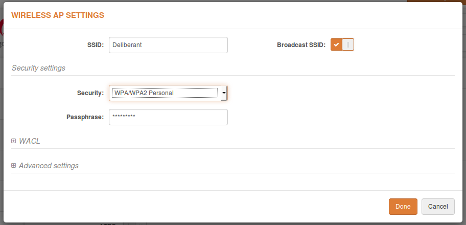
- set the SSID;
- enable Security, if necessary.
Station Configuration
Steps for configuring the Wireless tab on the Station:
based on the access point:
- select Country;
- set Wireless mode to Station (WDS/iPoll 2/iPoll 3).
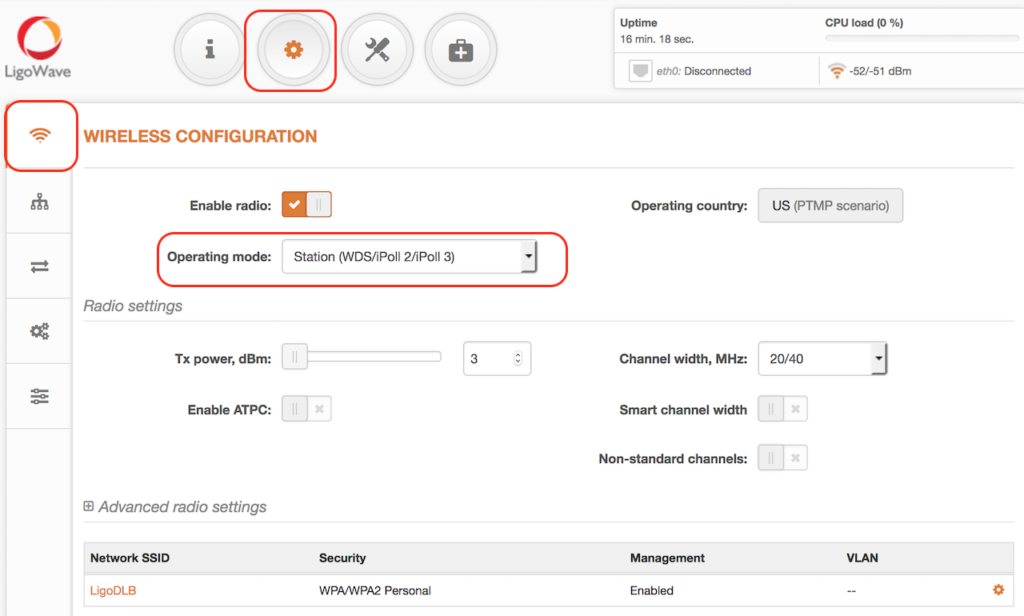
- enable Security, if necessary;
- set the SSID.
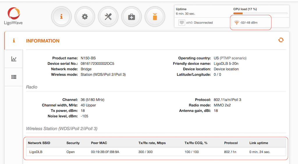
If the device is MIMO, there are two signal streams. One of them is Main (Antenna 1) and the other is Aux. Main’s stream is mandatory. If Main’s signal is very weak, the link will not be stable or will not work at all. It is necessary to align the antennas to achieve the best Main signal. If Aux’s stream is weak, the link will work at a lower data rate. Check whether the CCQ is good on the AP and the Station and whether it reaches 100/100.
Step 6. Optimize the channel size for best performance.
Configuration of a Point-to-Multipoint iPoll 3 Bridged Network
iPoll 3 mode can be set in a bridged (layer 2) network. iPoll 2 mode should be used when the AP and all of its stations are Deliberant devices. Otherwise, select the WDS mode. The recommended maximum number of stations per AP is 60–70.
Configuration of the iPoll 3 Mode
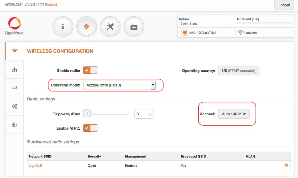
Steps for configuring the wireless settings for an iPoll 3 Master Device:
- set Wireless mode to Access Point (iPoll 3);
- set the SSID;
- set Channel to Auto;
- enable Security, if necessary.
All other settings should be left as their default values.
Station Configuration
Steps for configuring the Wireless tab on the Station:
based on the access point:
- select Country;
- set Wireless mode to Station (WDS/iPoll 2/iPoll 3).
- enable Security, if necessary;
- set the SSID.
If the device is MIMO, there are two signal streams. One of them is Main (Antenna 1) and the other is Aux. Main’s stream is mandatory. If Main’s signal is very weak, the link will not be stable or will not work at all. It is necessary to align the antennas to achieve the best Main signal. If Aux’s stream is weak, the link will work at a lower data rate. Check whether the CCQ is good on the AP and the Station and whether it reaches 100/100.
Step 6. Optimize the channel size for best performance.
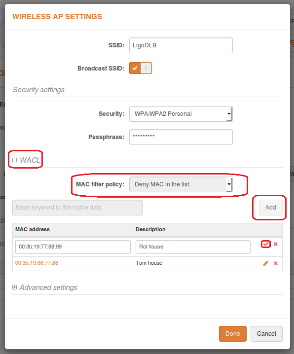
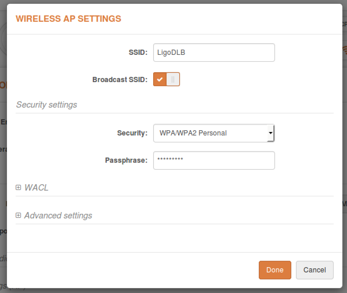
The Wireless Access Control List is an access control based on MAC addresses (only available in AP and iPoll 2 AP wireless modes). Access control allows users to limit wireless associations (based on the MAC address) with APs by creating an Access Control List (ACL).
The Wireless Access Control List is found in the Wireless AP settings:
To add a new rule, press Add:
- Open – no rules are applied.
- Allow MAC in the list – select to allow connectivity for devices in the list only (white list).
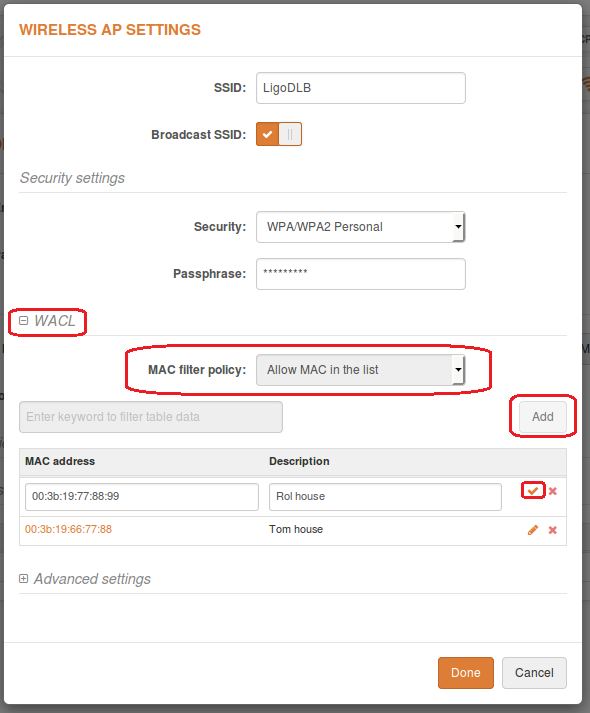
Deny MAC in the list – select to prohibit connection for devices in the list (black list).
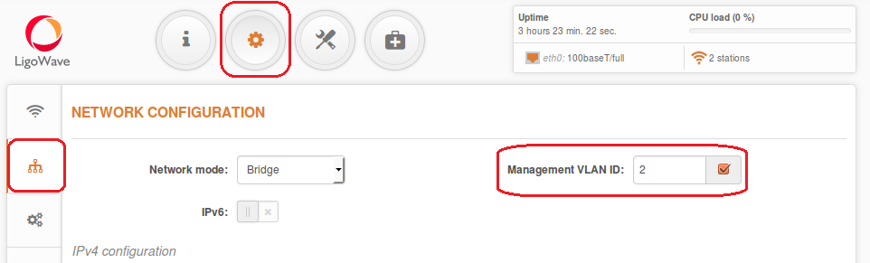
Virtual Local Area Networks (VLANs) are logical groupings of network resources.
- Enable management VLAN – enable VLAN tagging for management traffic. Access to the AP for management purposes can be further limited using VLAN tagging. By defining Management VLAN, the device will only accept management frames that have the appropriate Management VLAN ID. All other frames using any management protocol will be rejected.
- Management VLAN ID – specify the VLAN ID [2-4095]. When the device’s interfaces are configured using a specific VLAN ID value, only management frames that match the configured VLAN ID will be accepted by the device.
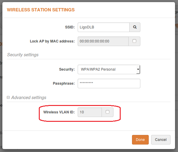
Map to data VLAN ID – specify the VLAN ID for traffic tagging on particular radio interfaces. Station devices that associate using the particular SSID will be grouped into this VLAN.
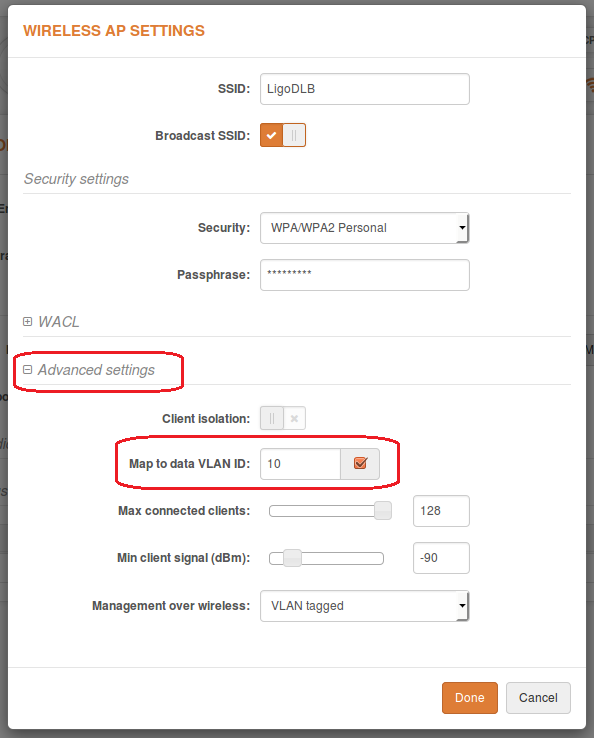
Enable Wireless VLAN ID on the Station device to enable data VLAN.
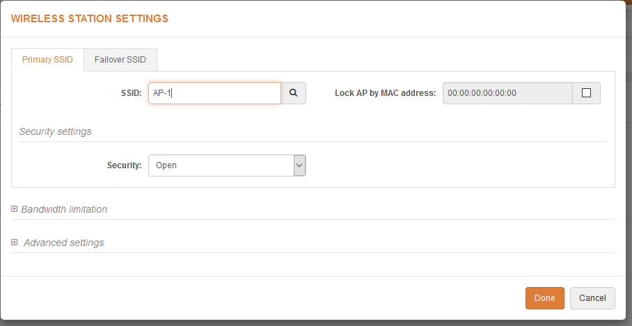
Step 1. Navigate to Configuration > Wireless configuration and set Operating mode to Station (auto iPoll 2).
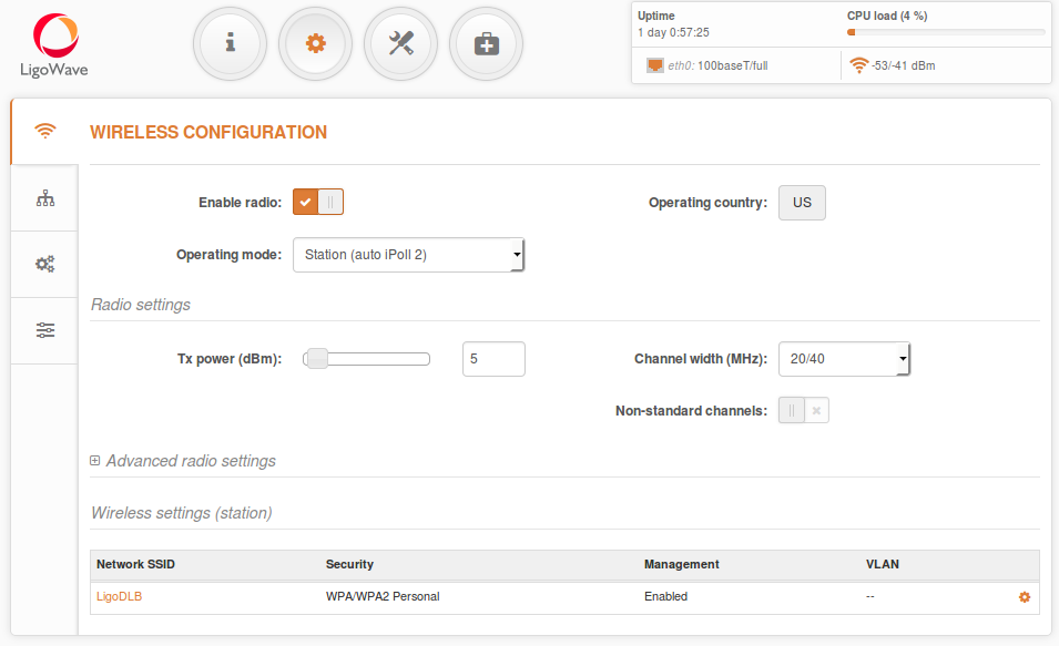
Step 2. Click on the little gear icon in the Wireless settings (station) table. In the newly popped-up window, specify the Security parameters for the AP and check whether all of the necessary settings match those of the AP, and then click Done:
Step 3. Verify the connection. Navigate to Status > Information. The information page will display wireless information on the link with access point. The connection status should be Connected and progress bars indicating the quality of the connection should be present:
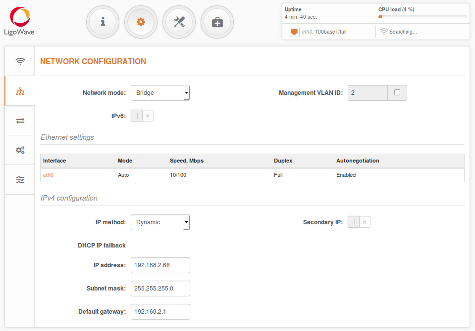
Router IPv4 Mode
Step 1. This section allows users to customize the parameters of the Router to suit the needs of the network. This includes the ability to use the built-in DHCP server. When the device is configured to operate as a Router, the following sections should be specified: WAN network settings, LAN network settings, and LAN DHCP settings.
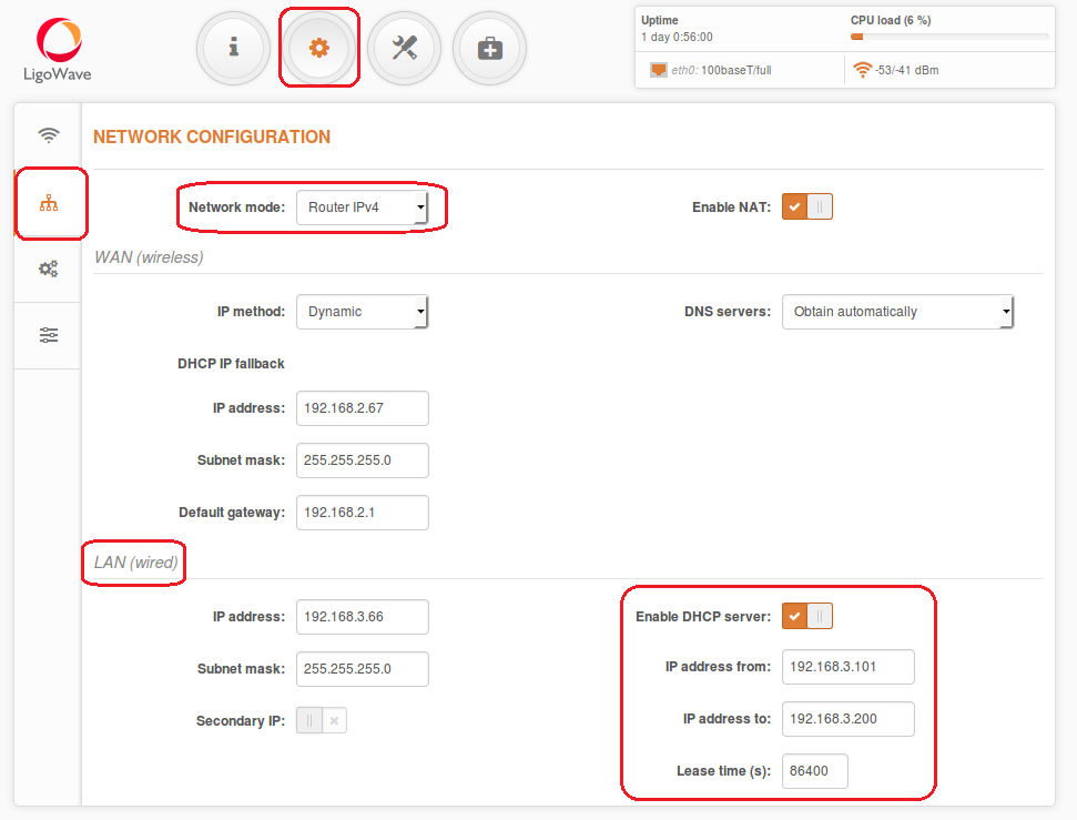
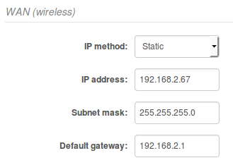
Step 2. WAN Settings. WAN network settings include options related to the WAN interface. In this scenario, the WAN interface is on the wireless side. The access type of the WAN interface can be configured to use Static IP or Dynamic IP.
WAN mode – set the IP method to Static to specify IP settings for the device’s WAN interface:
Step 3. DHCP mode – set up a server to enable the DHCP server on the LAN interface.
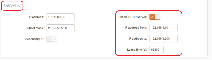
- IP address from – specify the starting IP address of the DHCP address pool.
- IP address to – specify the ending IP address of DHCP address pool.
- Subnet mask – specify the subnet mask.
- Default gateway – specify the DHCP gateway IP address.
- Lease time – specify the expiration time in seconds for the IP address to be assigned by the DHCP server.
- DNS server – specify the DNS server’s IP address on the WAN side.
Router IPv6 Mode
Step 1. To set up an IPv6 router, set the Network mode to Router IPv6 and specify the required WAN and LAN settings.
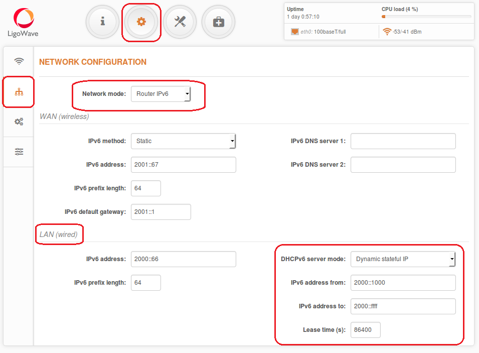
Step 2. WAN Settings.
WAN network settings include options related to the WAN interface. In this scenario, the WAN interface is on the wireless side. The access type of the WAN interface can be configured to use Dynamic stateless IPv6, Dynamic stateful IPv6, and Static IPv6.
WAN mode – set the IP method to Static IPv6 to specify IPv6 settings for the device’s WAN interface:
IPv6 WAN (wired) settings: Static. All settings must be specified manually with this method.
IPv6 WAN (wired) settings: Dynamic Stateless. With this method, the device generates its own IP address by using a combination of locally available information and router advertisements, but receives DNS server information from a DHCPv6 server. The IP address is dynamic.
IPv6 WAN (wired) settings: Dynamic Stateful. With this method, the device obtains an interface address, configuration information (such as DNS server information), and other parameters from a DHCPv6 server. The IP address is dynamic.
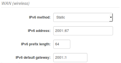
- IPv6 address – specify the IPv6 address for the Deliberant interface.
- IPv6 prefix length – enter the prefix length for the address (default is 64).
- IPv6 default gateway – specify IPv6 address for default gateway.
- IPv6 DNS server – specify the Domain Naming Server IPv6 addresses.
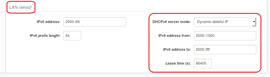
Step 3. DHCPv6 mode. Set up a server to enable the DHCPv6 server on the LAN interface.
Explanation of Parameters
- IPv6 prefix length – specify the IPv6 prefix length or keep the default prefix length (64).
- DHCPv6 server mode – select the required DHCPv6 mode from the drop-down menu:
- Disabled – select to disable the DHCPv6 server. No IPv6 addresses will be assigned to clients.
- Dynamic stateless IP – select for automatic IPv6 address configuration.
- Dynamic stateful IP – select to configure a stateful DHCPv6 server for the LAN by specifying the local DHCP IPv6 address pools, so that the DHCPv6 server can control the allocation of IPv6 addresses in the LAN.
- IPv6 address from – enter the start IP address. This address specifies the first of the contiguous addresses in the IP address pool.
- IPv6 address to – enter the end IP address. This address specifies the last of the contiguous addresses in the IP address pool.
- Lease time – specify the expiration time in seconds for the IP address assigned by the DHCPv6 server.
How to Configure a PPPoE Client?
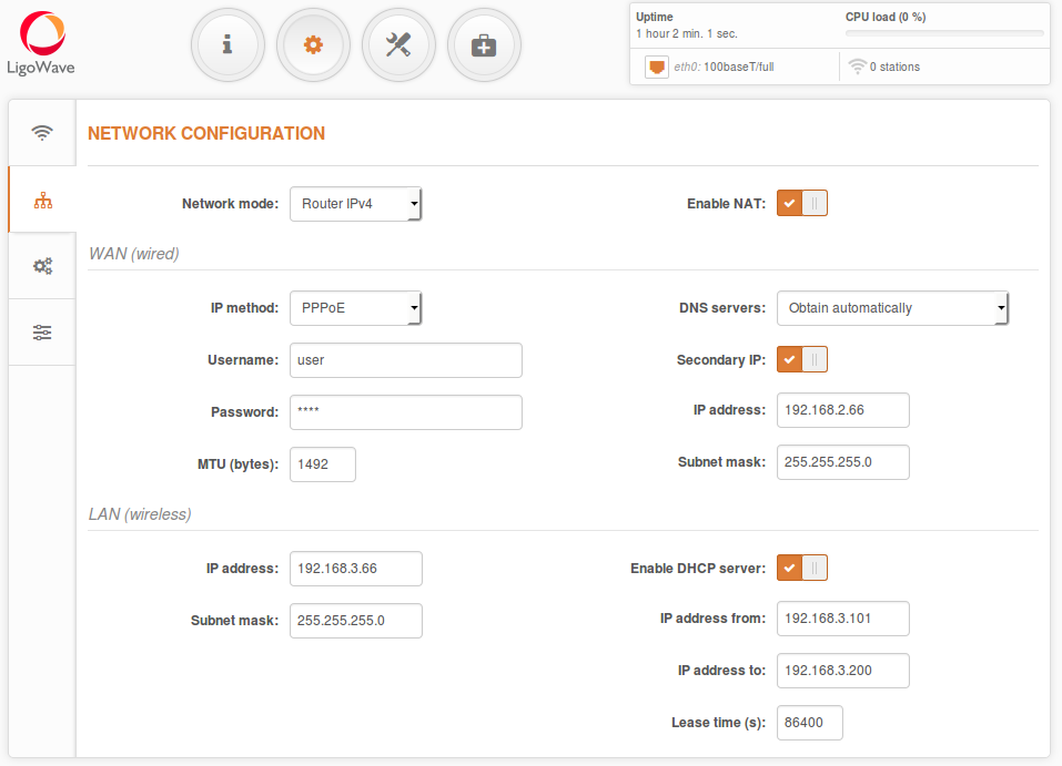
A DLB APC operating in Router mode will receive Internet data through the WAN port and will share it to the LAN ports, which will be separated by a different IP range. The type of connection to the WAN interface can be set by choosing Static IP, DHCP client, or PPPoE.
WAN mode – choose PPPoE to configure the WAN interface, so that it would connect to an ISP via a PPPoE.
The username and password should be added to the main configuration, while all other settings should remain as their default values.
Explanation of Parameters
PPPoE settings on the WAN interface:
- Username – specify the user’s name for PPPoE.
- Password – specify the password for PPPoE.
- MTU – specify the MTU (Maximum Transmission Unit) in bytes.
- Enable secondary IP – specify the alternative IP address and the netmask for LigoDLB unit management.
- DNS settings – allows users to determine whether automatically-assigned or alternative DNS servers should be used.
LAN Network Settings:
- IP address – specify the IP address of the device LAN interface.
- Subnet mask – specify the subnet mask of the device LAN interface.
- Enable DHCP server – select to enable DHCP server on LAN interface.
- IP address from – specify the starting IP address of the DHCP address pool.
- IP address to – specify the ending IP address of the DHCP address pool.
- Lease time – specify the expiration time (in seconds) for the IP address assigned by the DHCP server.
The LigoDLB series does not have HotSpot features in the firmware by default.
To enable UAM or Repeater features, follow these instructions:
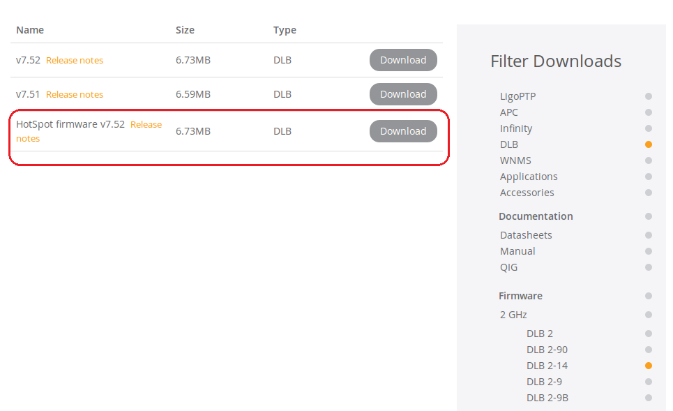
Step 1. Download the ZIP archive file from the LigoWave website—either for the LigoDLB 2/5 or the LigoDLB PRO 2/5 series, whichever you are using at the moment:
- LigoDLB 2 series firmware
- LigoDLB 5 series firmware
- LigoDLB PRO 2 series firmware
- LigoDLB PRO 5 series firmware
The archive should contain three files:
- the main firmware
- the default configuration firmware
- the ReadME file with upgrade instructions
Step 2. Upgrade the LigoDLB unit with the main firmware.
Step 3. Upgrade the LigoDLB unit with the default configuration firmware.
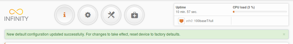
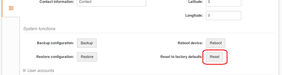
Step 4. Reset the device to its default factory settings.
Step 5. Follow the instructions on how to configure HotSpot and Repeater scenarios for the NFT device:
Step 6. Once configured, perform the firmware upgrade for the second time with the main image in order to set up the backup image for dual-boot.
How to Configure a Repeater
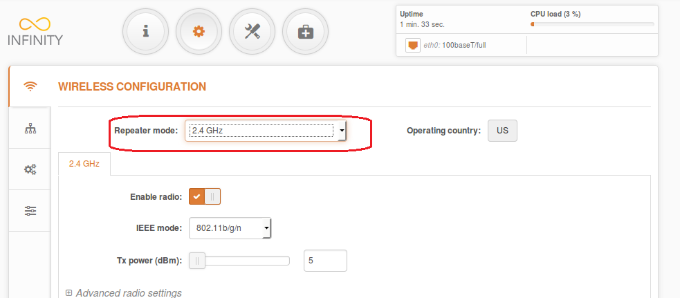
The LigoDLB series of devices does not have Repeater functionality set in the firmware by default. To enable Repeater mode, follow these instructions:
Step 1. First of all, the access point has to be configured to operate as a standard Access Point (Auto WDS).
Step 2. Configure the SSID and Security.
Step 3. Save & Apply the settings.
Step 4. To configure the access point to automatically receive network settings, set the IP method to Dynamic.
Step 5. Save & Apply the settings.
Step 6. Keep the access point on and either plug the LAN connection into a live network (modem, router, or switch), or simply unplug from the configuration computer.
Configure Repeater (Station Settings)
Step 1. Download the HotSpot firmware from LigoWave’s Downloads page.
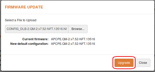
Step 2. Extract from archive the LigoDLB HotSpot firmware. There should be two files in this folder: DLB-2/5-HotSpot.QM-2/5.vXX.NFT.img and CONFIG_DLB-2/5.QM-2/5.vXX.NFT. NFT_for_DLB-2/5.OEM.img.
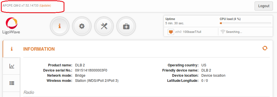
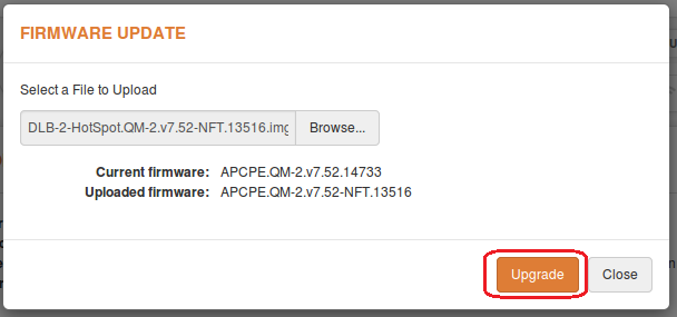
Step 3. Turn on the repeater device’s GUI and click Update at the top-left corner of the screen.
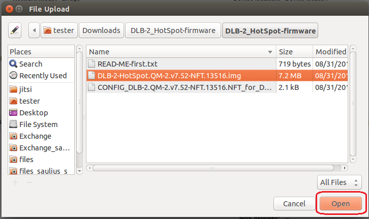
Step 4. In the device’s file upload screen, click Browse and navigate to the location of the extracted DLB-2/5_HotSpot-firmware folder and open the DLB-2/5-HotSpot.QM-2/5.vXX-NFT.img file.
Step 5. Upload and Upgrade the device.
Step 6. Click on Update on the top-left corner of the screen:
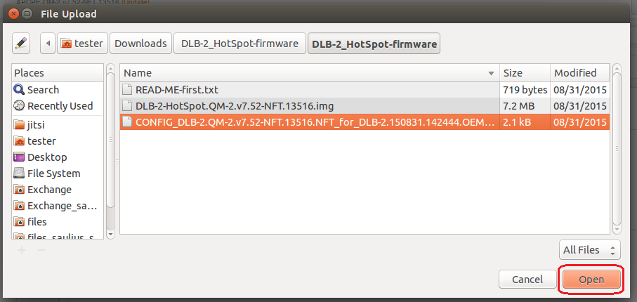
Step 7. In the file upload window, click Browse and navigate to the location of the extracted DLB-2/5_HotSpot-firmware folder.
Step 8. Select CONFIG_DLB-2/5.QM-2/5.vXX-NFT.NFT_for_DLB-2/5.OEM.img and click Open:
Step 9. Upload the file.
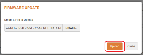
Step 10. Upgrade the device.
Step 11. Once the update is complete, reset the device to its default factory settings.
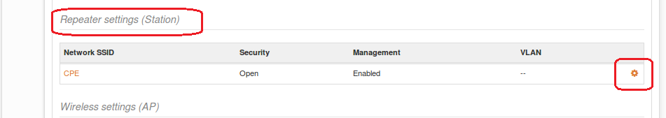
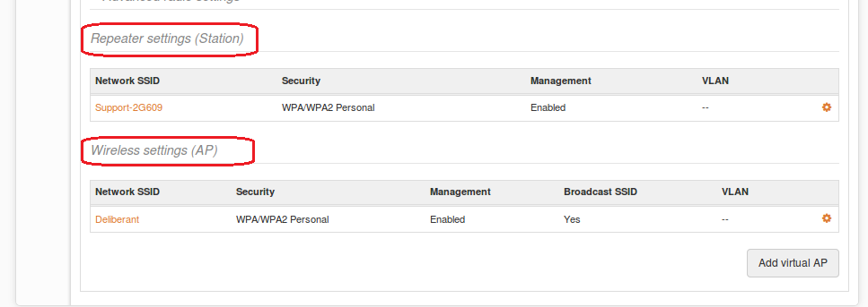
Repeater Configuration
Step 1. Log in and enable the Repeater mode.
Step 2. Click on the configuration gear icon under Repeater settings (Station).
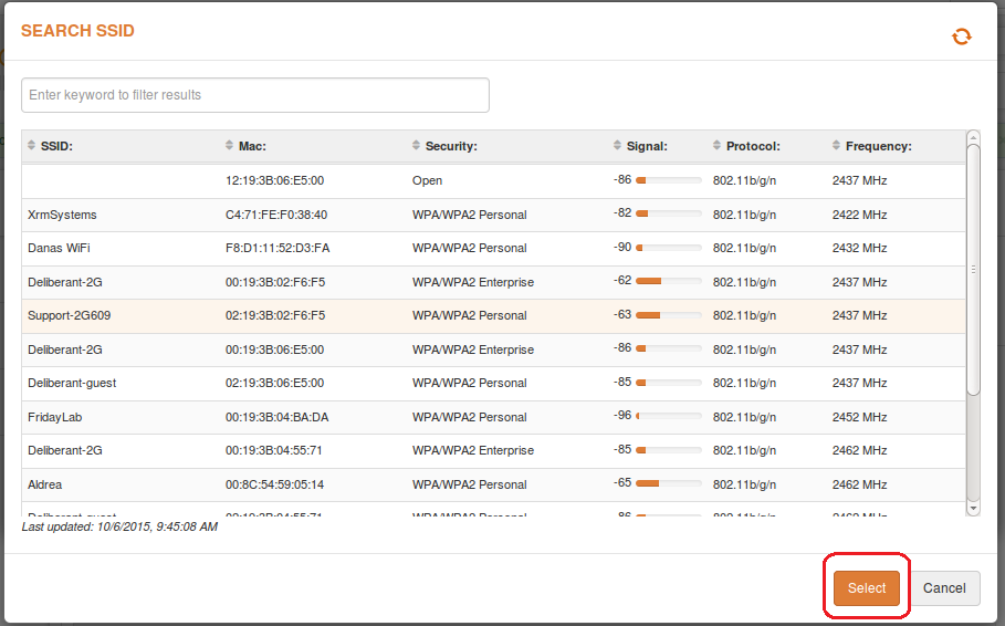
Step 3. Click on the magnifying glass icon to search for the access point.
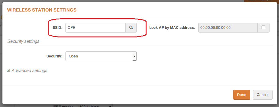
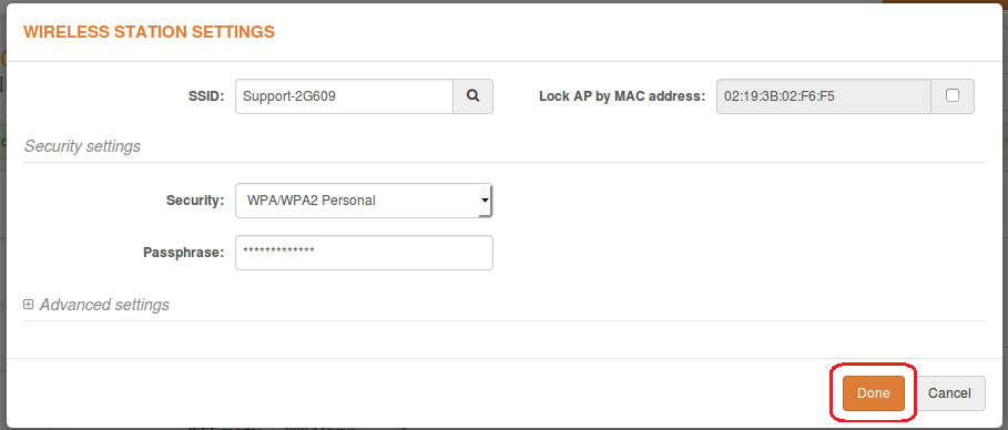
Step 4. Choose the necessary access point from the list and select the same security settings as the access point.
Step 5. Click Done once the configuration is finished.
Step 6. Check whether the Repeater (Station) and Access Point are configured correctly.
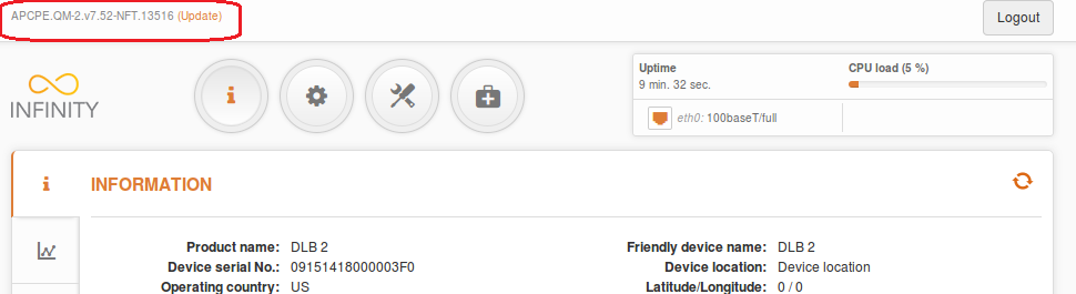
Step 7. Verify that the repeater is connected by going to the Information page.
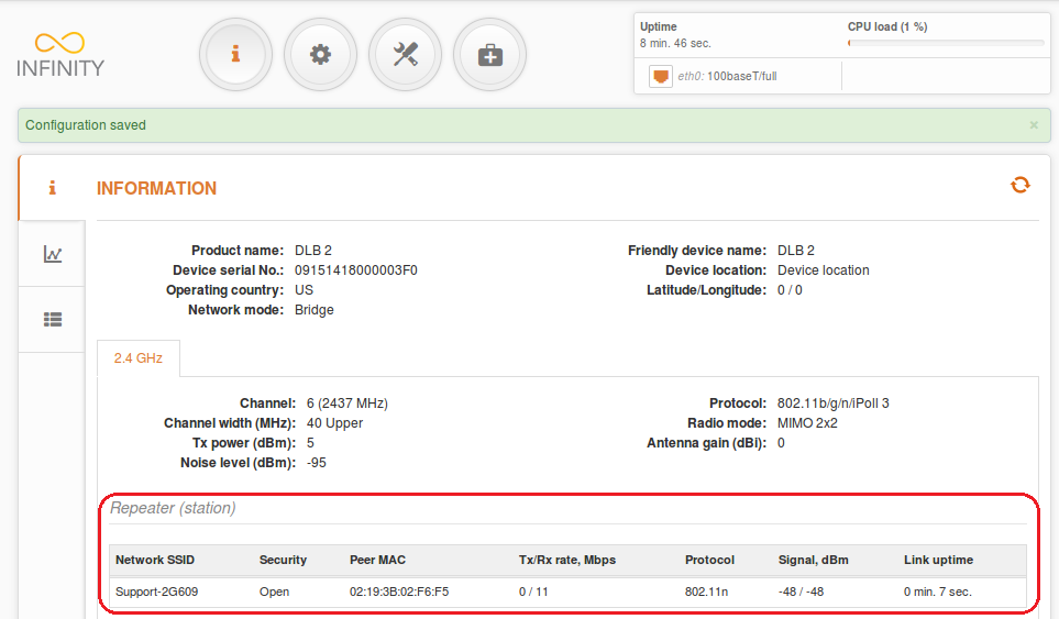 Confirm that the device is connected to the repeated SSID by going to the Information page on the repeater. The access point and repeater should now be ready to install.
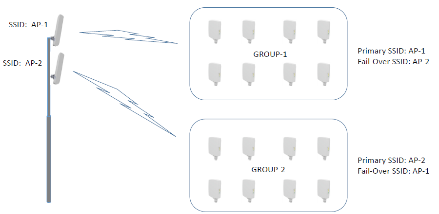
Failover SSID
LigoDLB units can connect to a pre-configured failover SSID in case the connection to the primary SSID is lost.
Use the Primary SSID tab to specify the Main Access Point SSID.
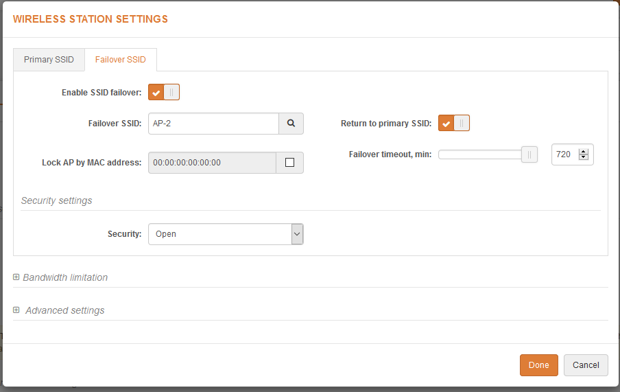
- Failover SSID – specify the secondary SSID where the LigoDLB Station will try to connect.
- Return to primary SSID – when enabled, the LigoDLB unit tries to connect continuously to the primary SSID in the intervals preset.
- Failover timeout – specify the amount of time in minutes for the station to attempt to connect to the primary SSID.
- Bandwidth limitation:
- Outgoing (AP to Station) – specify the maximum speed in Mbps of outgoing traffic.
-
Incoming (Station to AP) – specify the maximum speed in Mbps of incoming traffic.
Setup Example:
iPoll is a superior upgrade to the standard HCF (Hybrid Coordinate Function) technique. Without iPoll, any device will
transmit data without timing and coordination. HCF will cause frequent collisions when CPEs are sending data to the same
AP. Each collision will cause a random backoff timer before the CPEs can transmit data again. Multiple collisions will cause
a major drop in throughput and performance for the entire network. iPoll overcomes these common problems and yields
drastically better performance results in the same situation compared to standard HCF technology based networks.
The proprietary iPoll protocol allows each wireless link to obtain maximum bandwidth with the lowest possible latency. This is accomplished by utilising a smart polling feature which handles connected clients’ activity. Stations, which require less airtime are moved to a low activity or idle list, while stations, which are generating more traffic are moved to an active list. By decreasing the number of polled stations we achieve lower latency figures as well as higher throughput per station. The uplink/downlink ratio is implemented to control the throughput from the access point to stations. This ratio is dynamic and adjusts based on the active number of stations. The dynamic uplink/downlink ratio together with QoS makes LigoDLB device based networks self-optimizing and able to achieve maximum performance in different conditions.
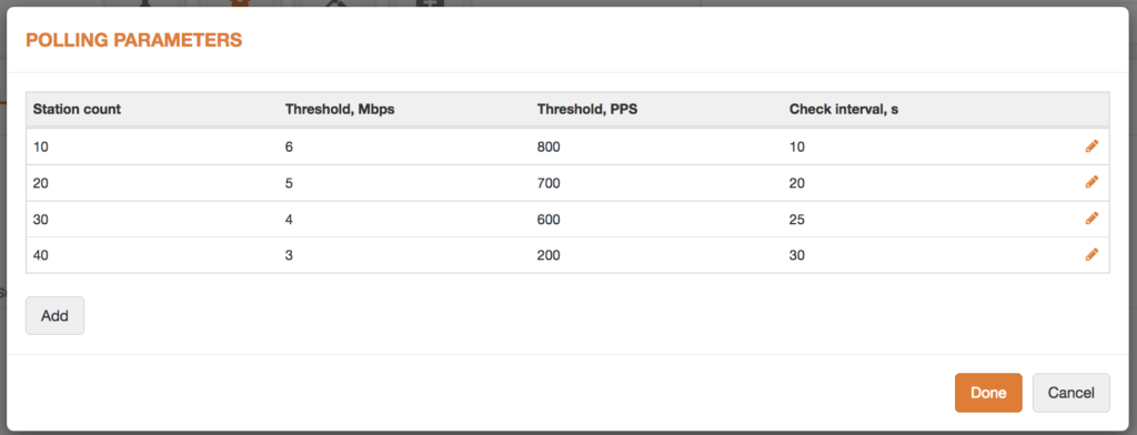
Station Count: Number of stations from which polling rules will be applied
Threshold, Mbps: Aggregate station throughput Mbps from which it will be started to poll
Threshold, PPS: Station PPS from which it will be started to poll
Check Interval, s: Thresholds checking interval in seconds
How to use polling parameters for PTP to get max capacity and low latency
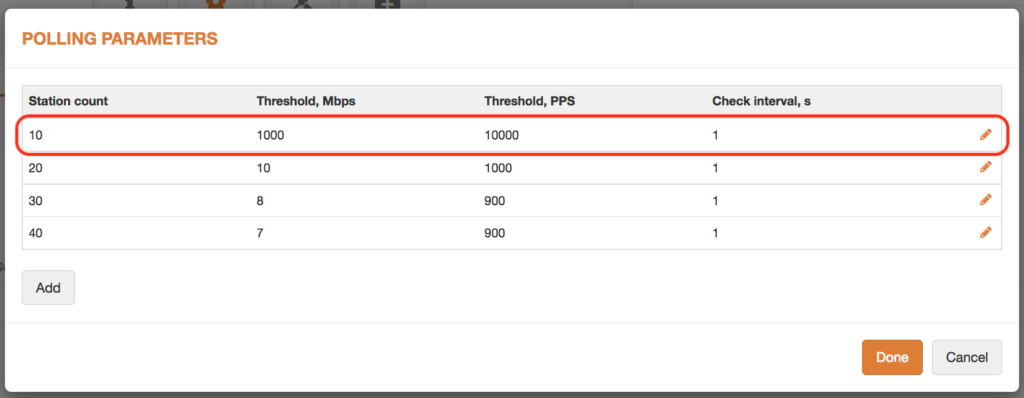
Note: For the PTP mode will be used only first rule which shows that polling will not start.
Advantages: low latency and higher maximum throughput
Disadvantages: packet loss and unexpected jitter
How to use polling parameters for PTP to get low jitter and low packet loss
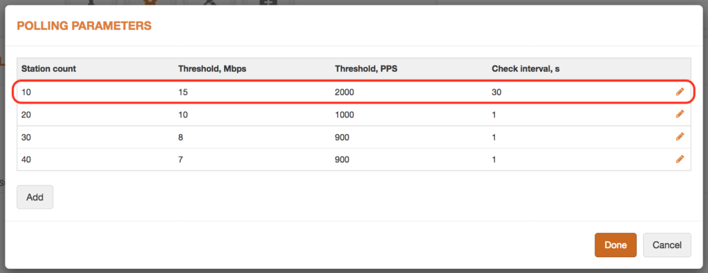
Note: For the PTP mode will be used only first rule which shows that polling will start when station reach 15Mbps aggregate throughput or 2000PPS.
Advantages: low packet loss and jitter control at high throughput
Disadvantages: increased latency
How to use poling parameters for PTMP to get low latency and max capacity
Note: For the PTMP mode will be used rules which shows that polling will start when station count exceeds 0-20, 20-30, 30-40, 40 or more.
Advantages: low latency and higher maximum throughput
Disadvantages: packet loss and unexpected jitter
How to use poling parameters for PTMP to get low jitter and low packet loss
Note: For the PTMP mode will be used rules which shows that polling will start when station count exceeds 0-20, 20-30, 30-40, 40 or more.
Advantages: low packet loss and control of high throughput stations
Disadvantages: increased latency