When a link is not working well, there are several solutions that users can implement:
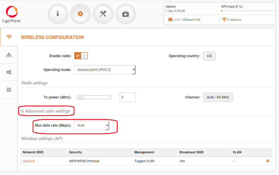
Solution #1. Reduce Max data rate by half. This can be done in Settings > Wireless Configuration. If this does not help solve the issue, then the problem may line in the fact that there are too many other access points operating on the current channel.
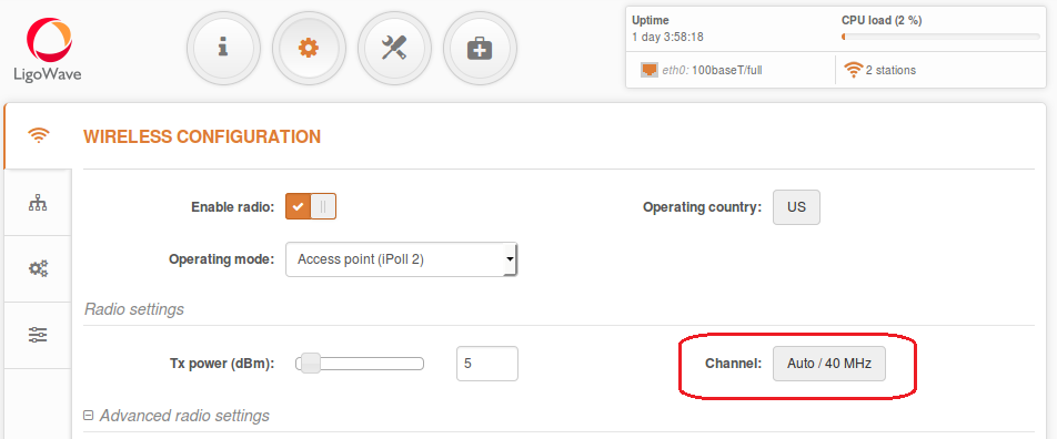
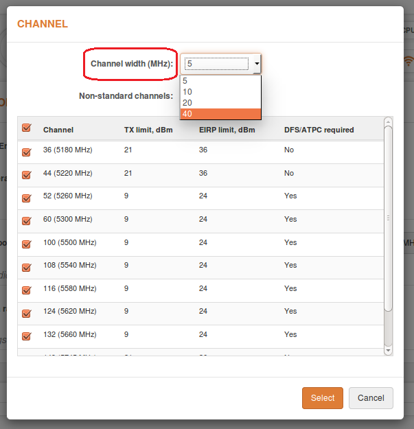
Solution #2. Set Channel width to the lowest available value. To do so, navigate to Settings > Wireless Configuration and change the value indicated near the Channel option.
The available channel widths are 5, 10, 20, and 40MHz.
Solution #3. Look for a better channel. To do so, navigate to Tools > Spectrum Analyzer, click Start, and wait for at least 20–30 seconds until the radio gathers enough packets to present real time noise.
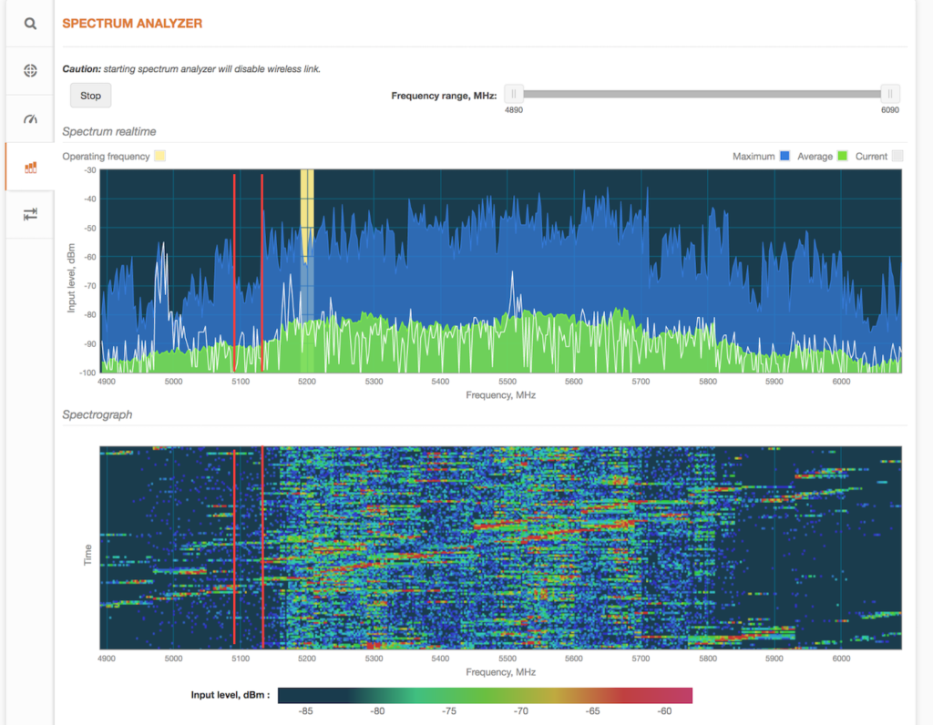
If the current channel shows high levels of noise (as indicated by the high bars in the picture above), look for a frequency range where noise levels are the lowest. The example above shows that the frequency range with the lowest level of noise is 5,750–5,800MHz.
Solution #4. Avoid collision with other access points by looking for the right channel. This can be performed with the Site Survey tool found under Tools > Site Survey.
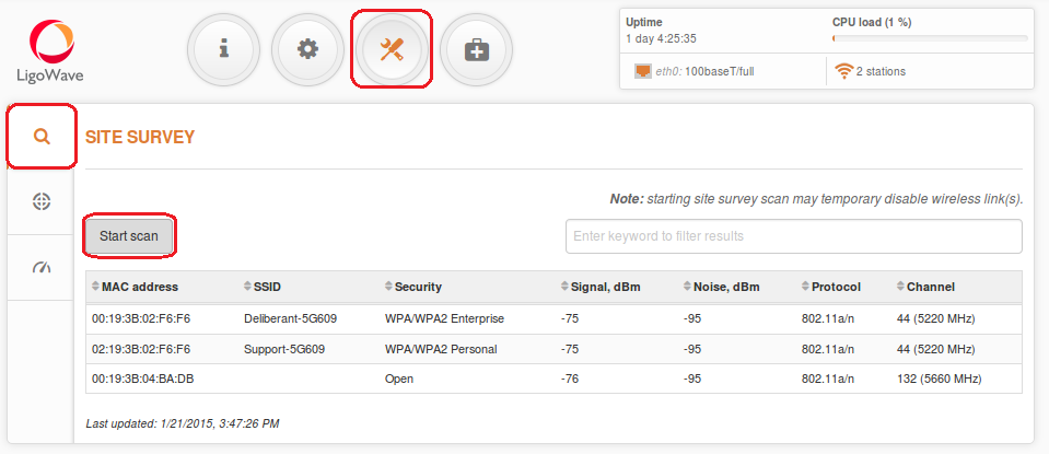
Choose a channel number that does not match the number in the Channel column and which would also have have clear range. This can be done in Settings > Wireless Configuration.
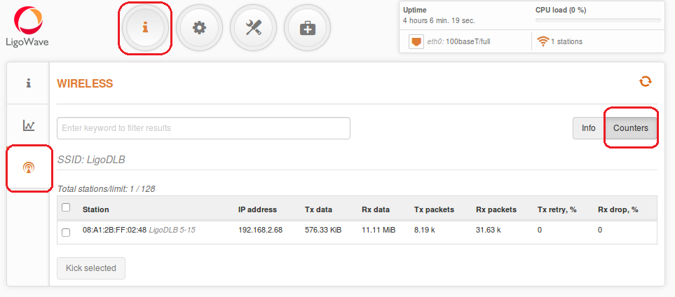
Once the link is established, test ping times and speed. If the results are not satisfactory, try another channel. Check the detailed statistics on the Tx retry % and Rx drop %.
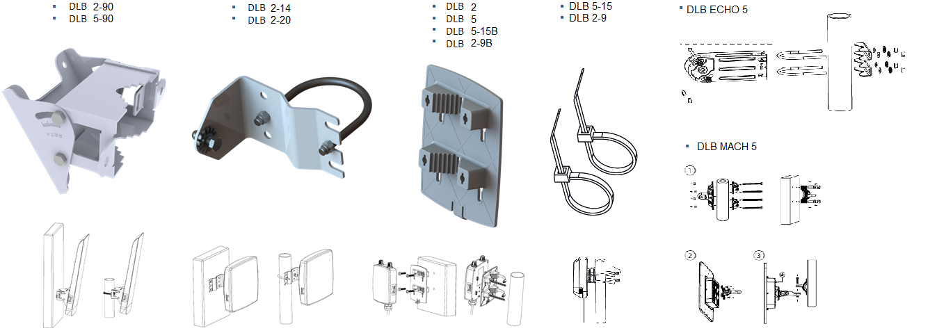
Outdoor Installation
There are three types of mounting plates. All of them can be mounted on walls or poles.
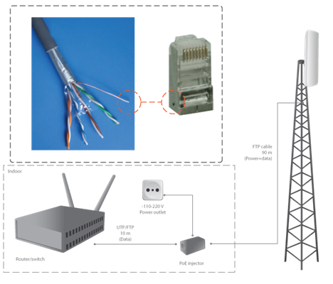
Cables
- length of cable connecting the switch and the DLB device, <100m;
- use FTP cable outside;
- use shielded RJ45 plugs outside;
- it is recommended to solder the drain wire to the RJ45 plug;
- use UTP or FTP cable inside.
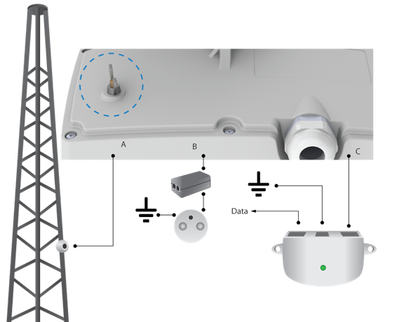
Grounding
Three grounding options are available:
- grounding stud on housing (only DLB 5M-20/90, Echo 5, Mach 5, 2M-14/90);
- grounding with PoE adapter B;
- grounding with PoE inserter C;
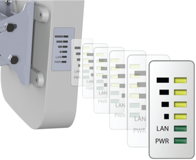
Alignment
Observe signal levels on the LED indicators:
- align both sides of the PTP link at the same time
- align the CPE in a multipoint network;
- standard RSSI thresholds are the top four LEDs.
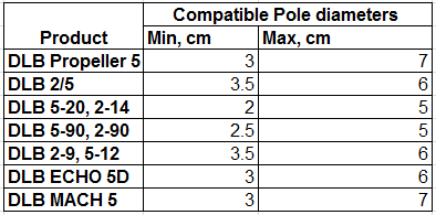
All LigoDLB devices can be mounted on a pole. The minimum and maximum pole diameter sizes are provided here:
The Antenna Alignment Tool measures the signal quality between the Master and Slave devices. To achieve the best results when aligning antennas, turn off all wireless networking devices within range of the device, except the device (or devices) with which you are trying to align the antenna. Watch the display for real-time feedback as you adjust the antenna.
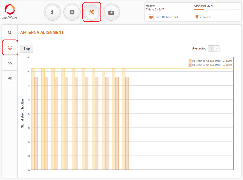
Start/Stop – press to start or to stop antenna alignment.
Averaging – if enabled, the graph will display the average signal strength of both vertical and horizontal polarities.
Proper Antenna Alignment
1. Disable ATPC functionality;
2. Set the maximum Tx power;
3. Choose the compliance testing country code during installation.
Once alignment is completed, choose your country code and enable ATPC functionality.