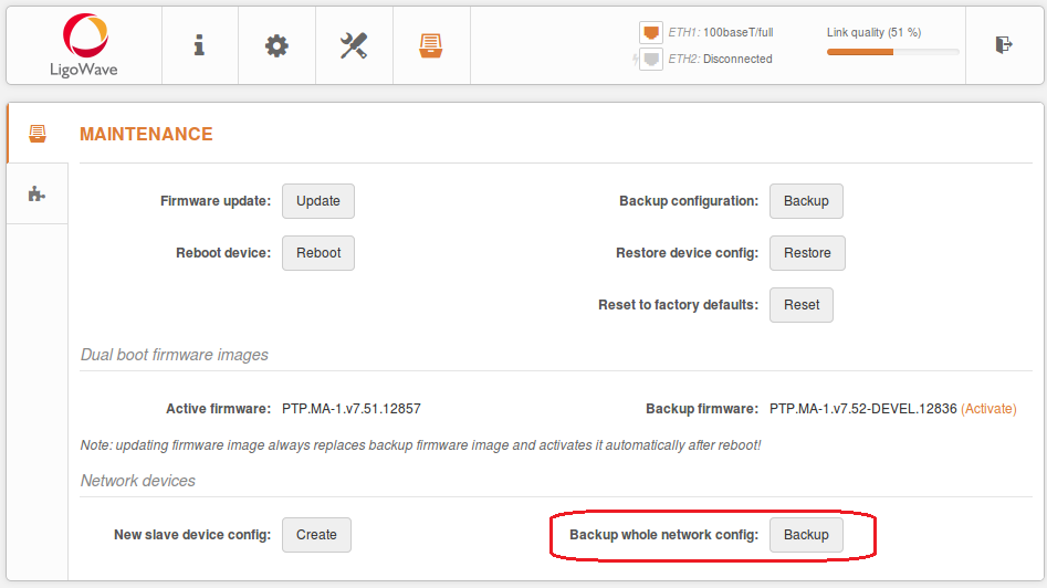
Most LigoWave devices have the dual firmware image feature.
If a device fails to perform a firmware boot from an active partition 3 times, it will set the second partition as the active one and will boot from the backup partition.
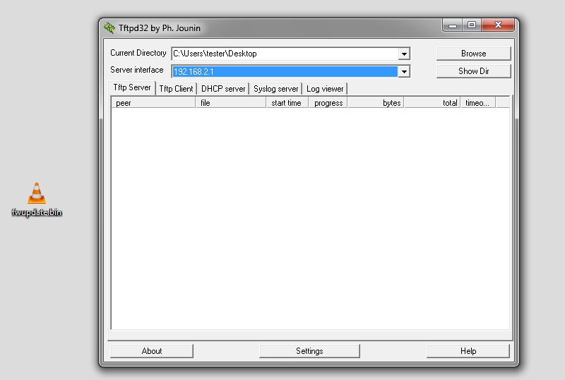
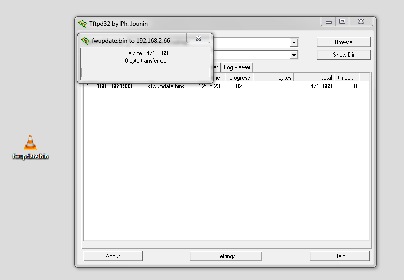
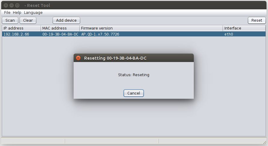
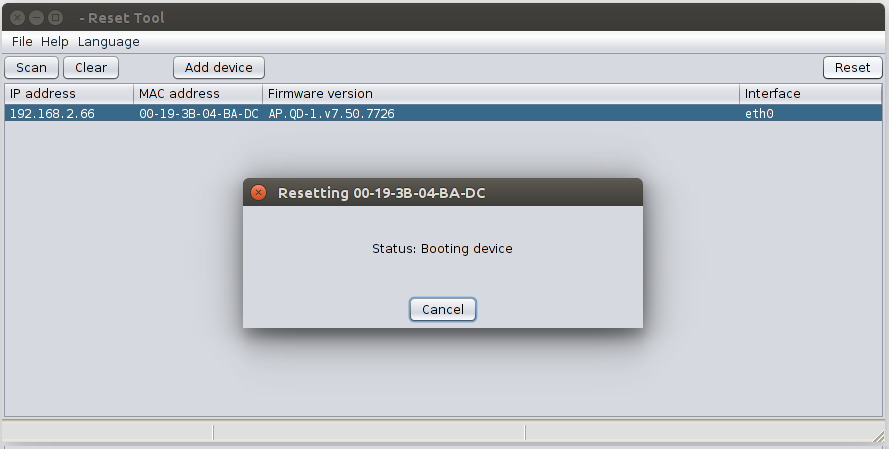
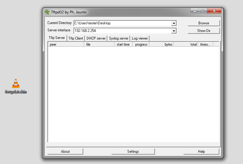
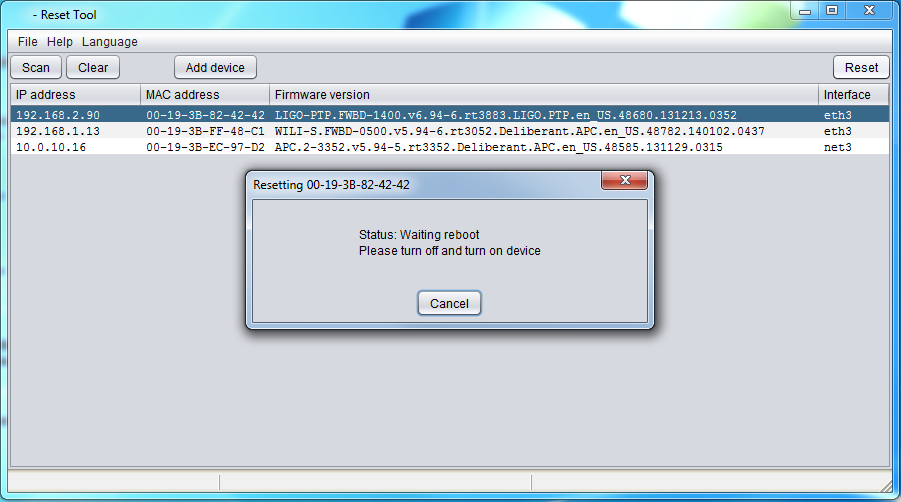
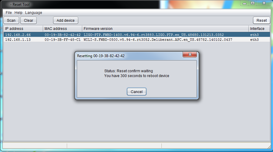
If a device fails to perform a firmware boot from both partitions 3 times, it will enter recovery mode. Then it will wait 5 minutes for a new firmware image via TFTP.
If no image is supplied to the device, it will try to boot images from both partitions again.
The following devices support the dual firmware image feature:
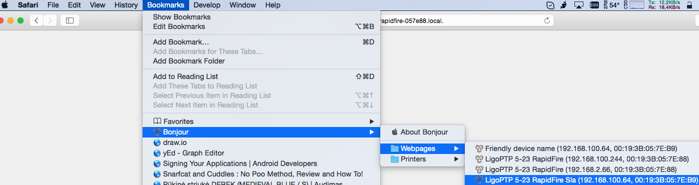
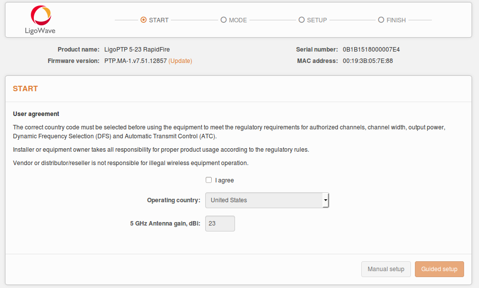
– LigoPTP RapidFire
– LigoDLB
– LigoDLB PRO
– LigoDLB ac
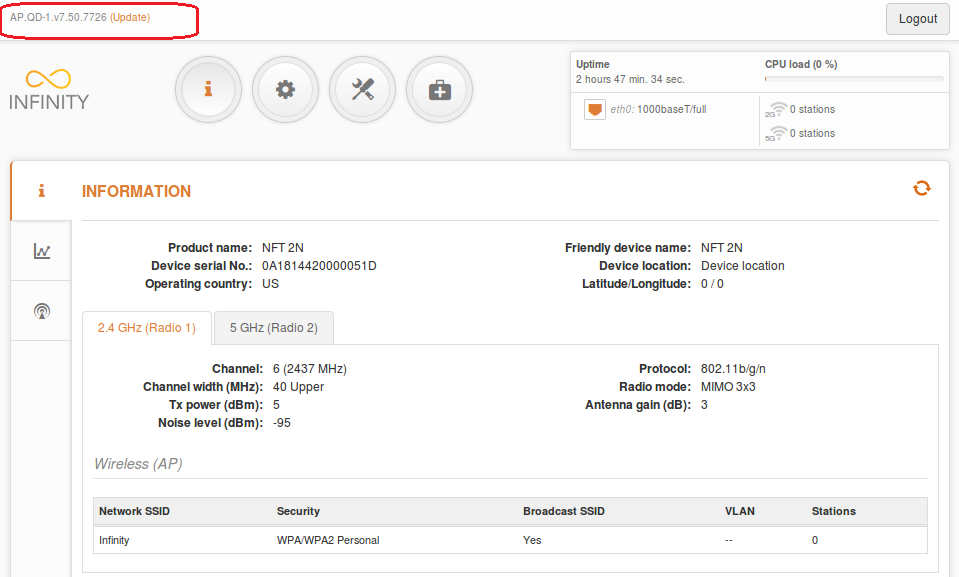
– Infinity
The following devices do not support this feature:
– NFT 2AC
– LigoDLB 5-15ac
– LigoDLB 5-20ac
– LigoDLB 5-90ac
– LigoDLB 5ac
– LigoDLB 6-15ac
– LigoDLB 6-20ac
– LigoDLB 6-90ac
– LigoDLB 6ac
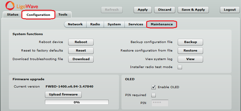
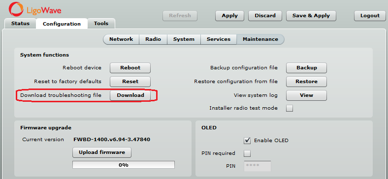
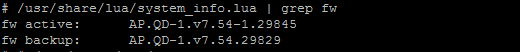
Follow these steps to check the active and backup firmware versions on the devices:
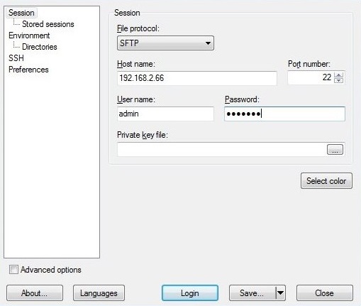
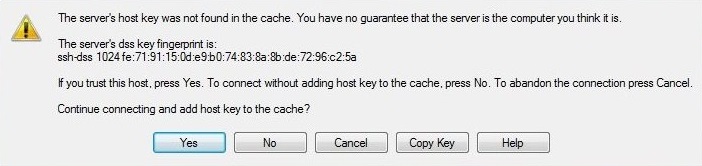
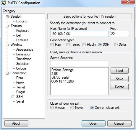
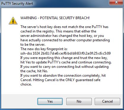
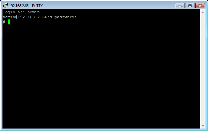
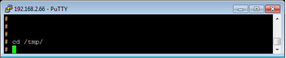
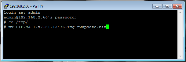
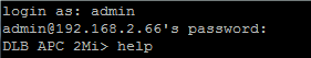
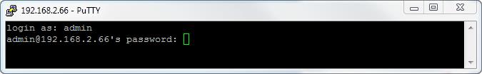
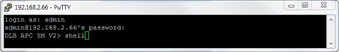
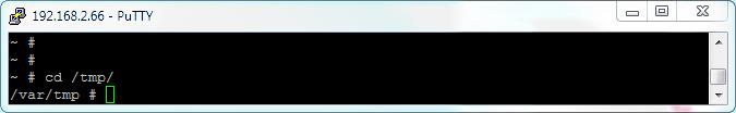
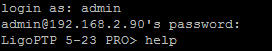
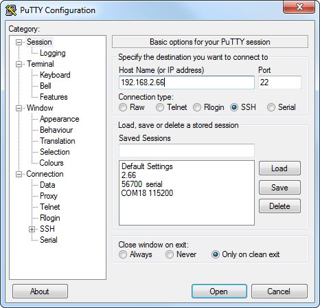
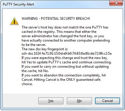
Step 1. Log in into the device via SSH.
Step 2. Run the following command: /usr/share/lua/system_info.lua | grep fw
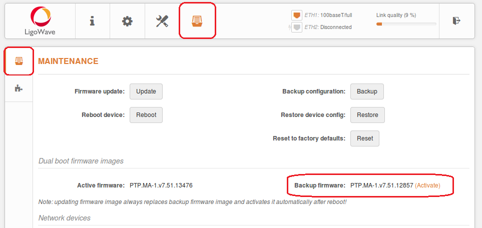
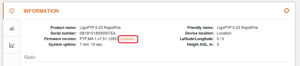
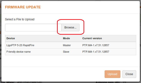
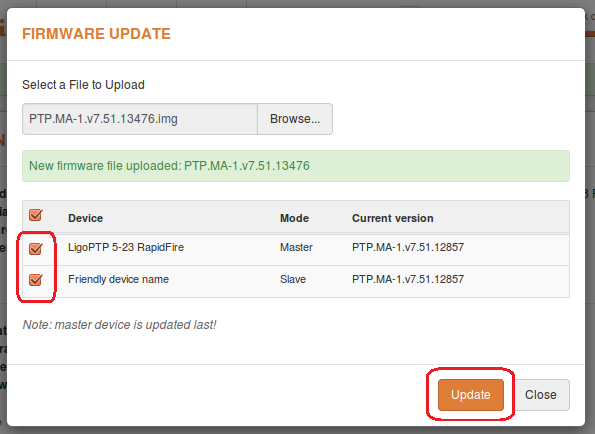
Information about how to check active firmware or how to activate backup firmware on the RapidFire device can be found here:
https://www.ligowave.com/wiki/faq/ligoptp-rapidfire-active-and-backup-firmwares/