Guided Point-to-MultiPoint (PTMP) Link Setup
Follow these steps when connecting to the LigoPTMP Web Management Interface for the first time:
Step 1. Launch the web browser.
Step 2. Enter the device’s default IP address in the browser’s URL field. The IP address is assigned from the network’s DHCP server.
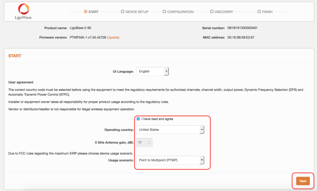
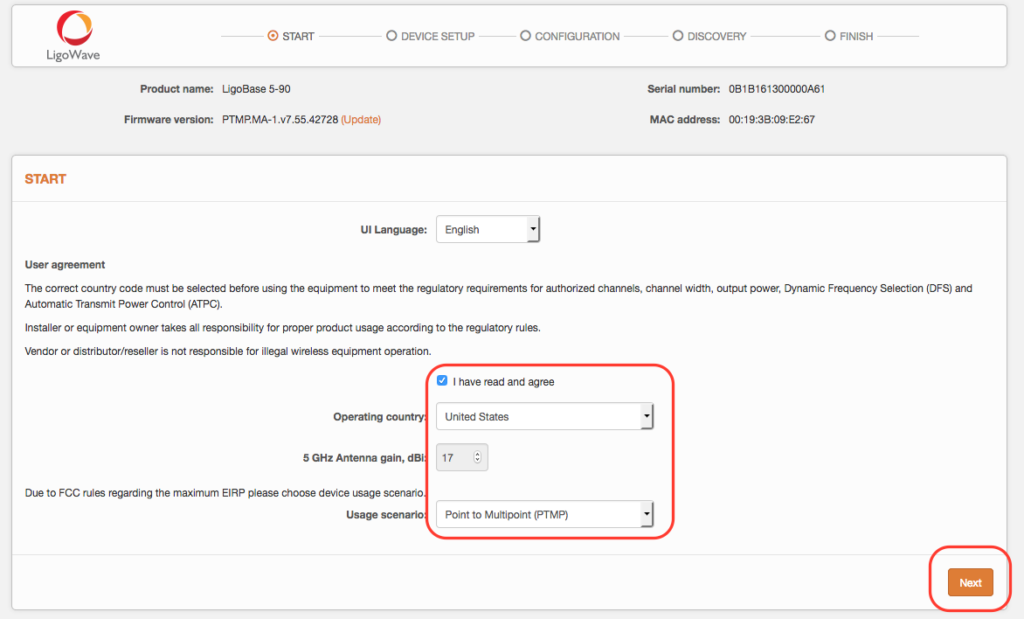
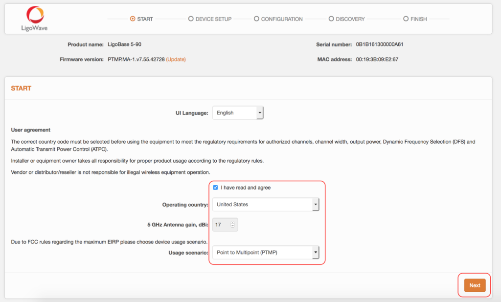
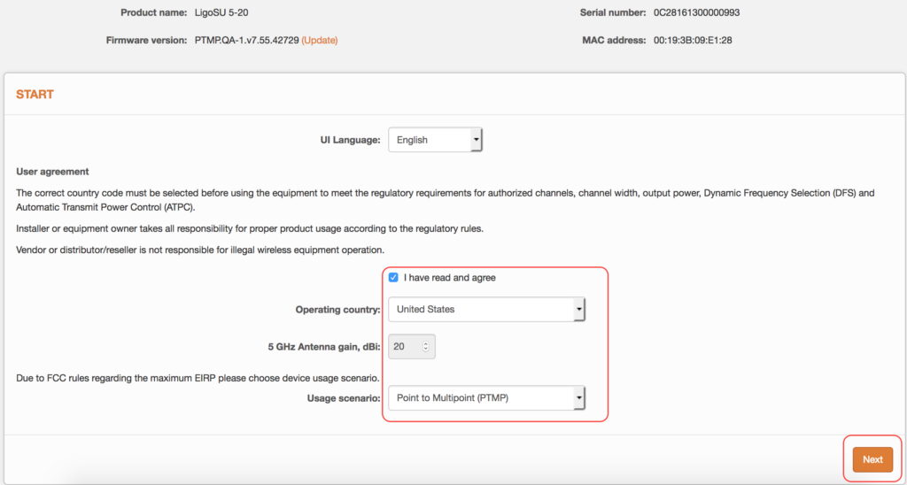
Step 3. The LigoPTMP unit should load the user agreement page by default (out of the box or if reset to default settings).
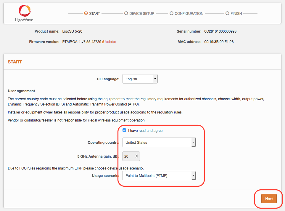
Step 4. Once the user agreement is signed, select the LigoPTMP’s country of operation. Regulatory domain settings may differ depending on the selected country. Users will not be allowed to select radio channels and radio frequency output power outside of the values permitted by the regulatory domain of the selected country.
Antenna gain should be set for products with external antenna only.
Step 5. Once the country is selected, click Next to start the LigoPTMP unit’s installation:
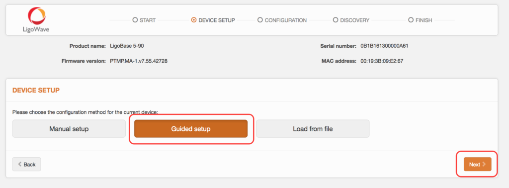
Guided LigoBASE Setup
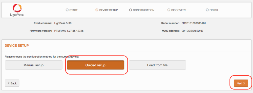
Click Guided setup to start the installation of the LigoPTMP device:
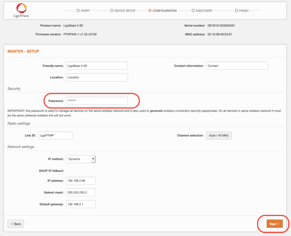
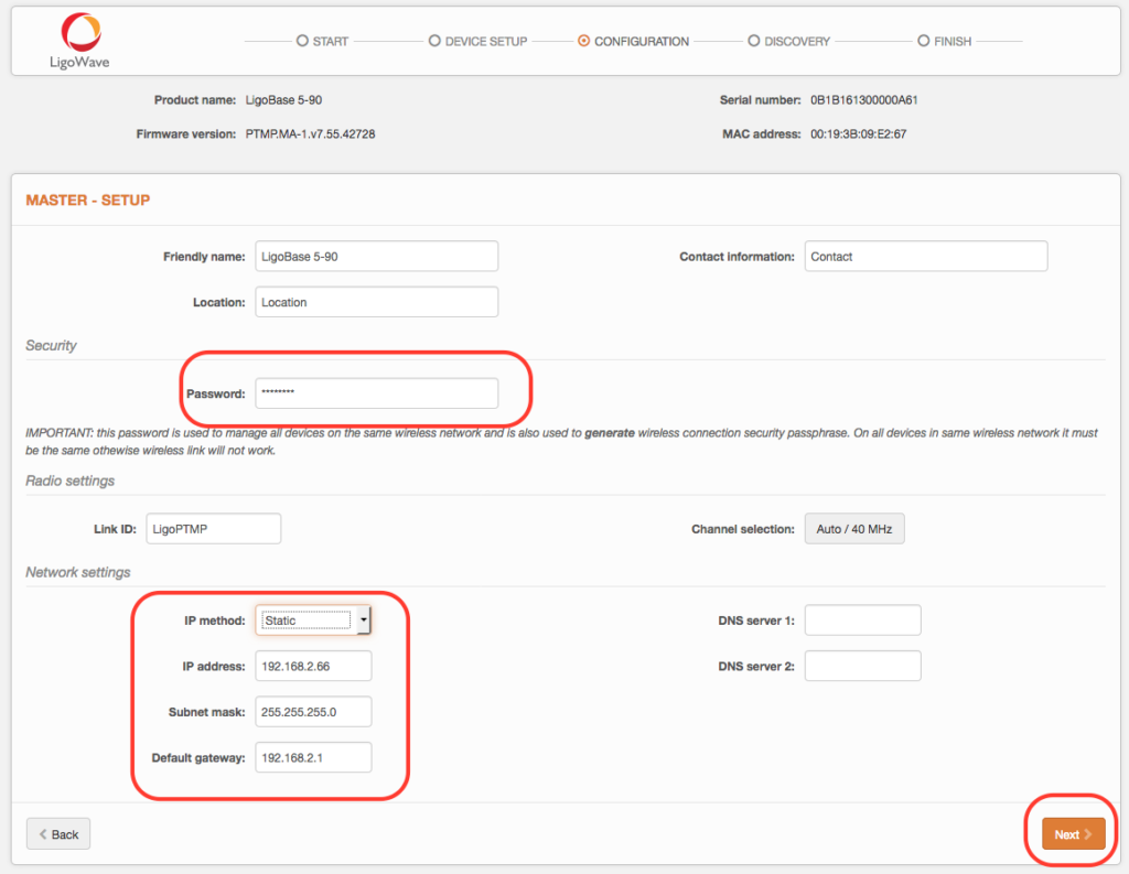
Specify the essential parameters of the LigoBASE (Master) unit and click Next:
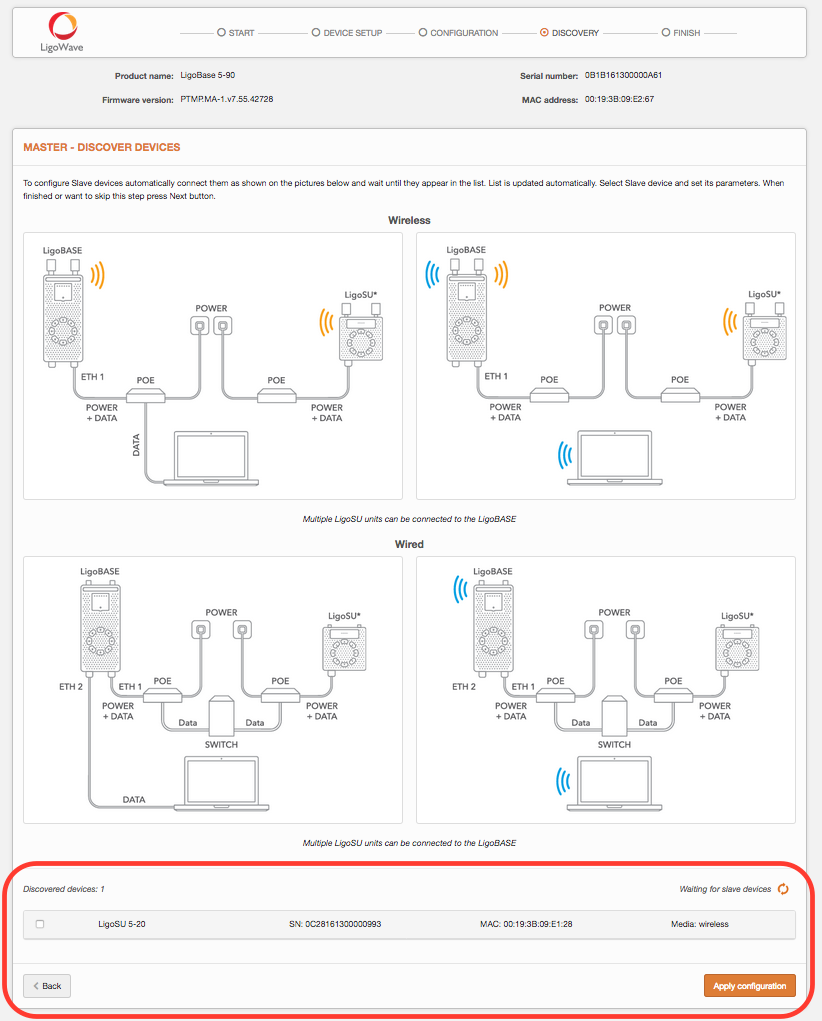
Connect the LigoSU unit to the LigoBASE unit as shown in the pictures below (select one of the given connection options) and wait until the LigoSU unit appears in the list at the bottom of the page:
![]()
Select the discovered LigoSU unit and assign the following parameters: IP address, Friendly name, and Location.
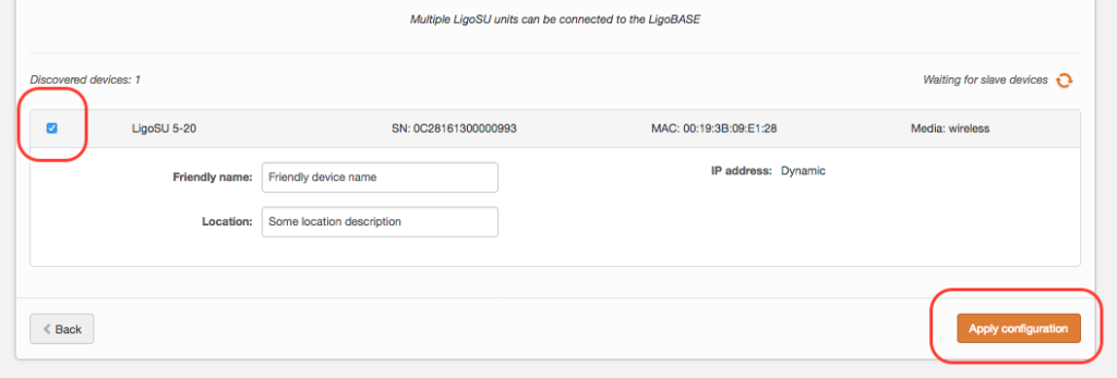
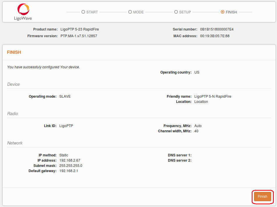
Click Apply configuration and review the LigoPTMP link’s assigned settings:
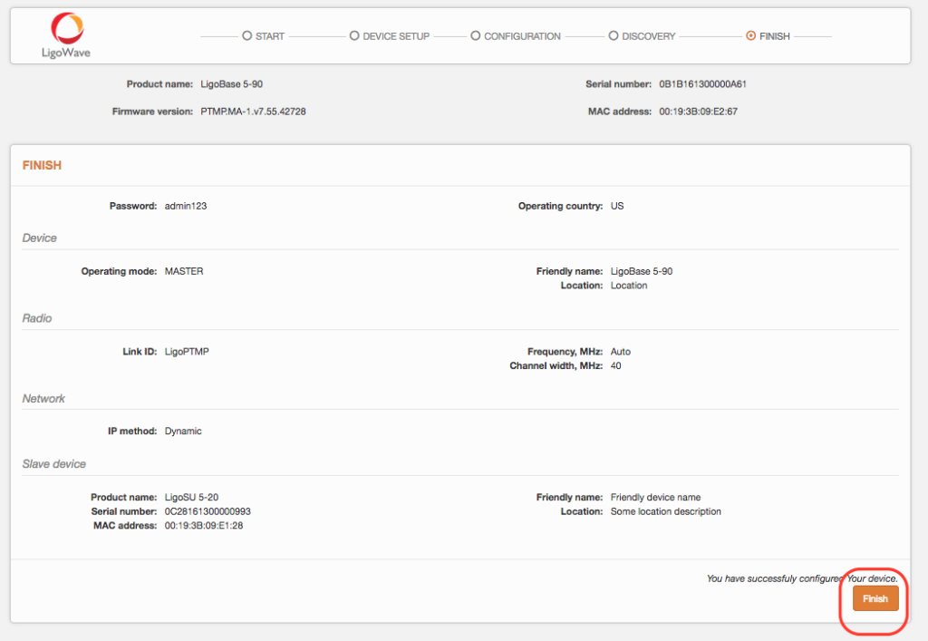
Click Finish to enable and apply the newly assigned settings to both units of the LigoPTMP link.
The LigoPTMP link is now successfully configured.
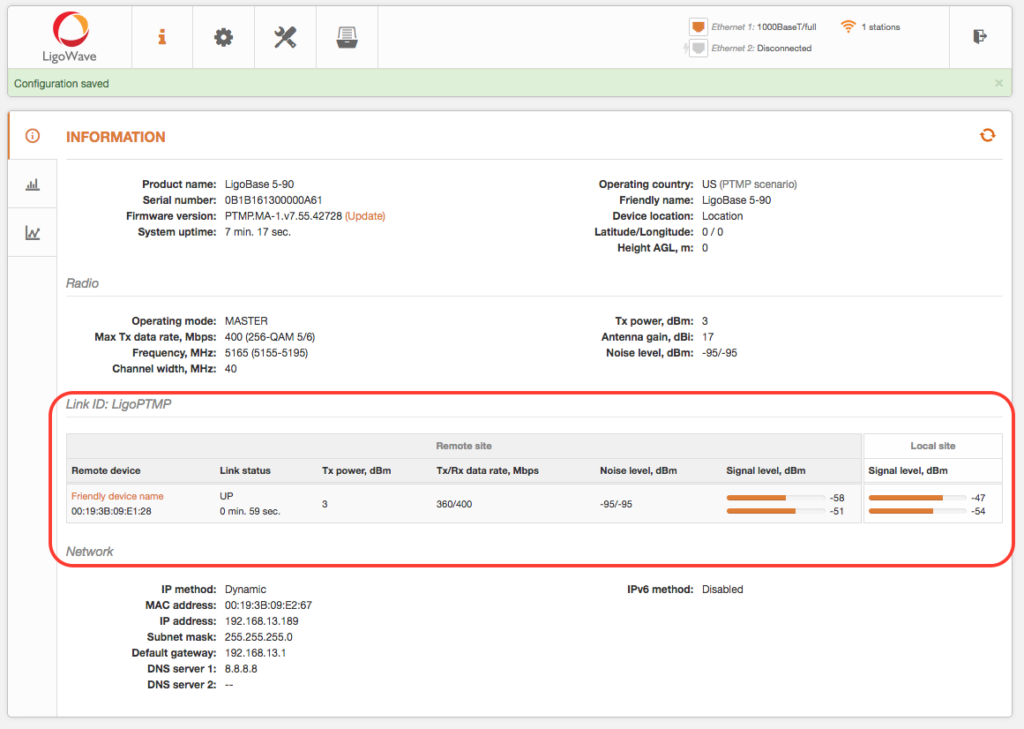
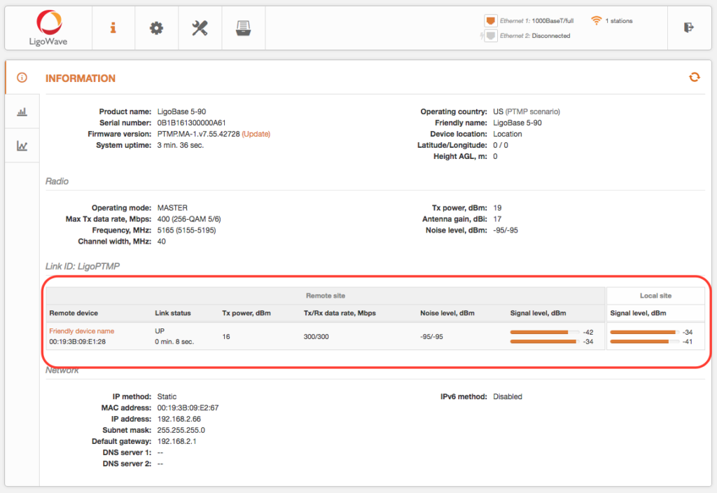
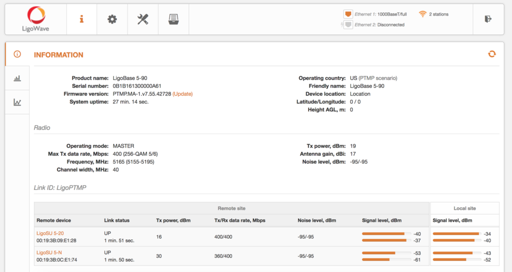
Check the parameters of the established link on the LigoBASE unit at Status > Information:
Guided Point-to-MultiPoint (PTMP) Link Setup
alert style=”info”]This configuration example is for the LigoPTMP series of devices only.[/alert]
Follow these steps when connecting to the LigoPTMP Web Management Interface for the first time:
Step 1. Launch the web browser.
Step 2. Enter the device’s default IP address 192.168.2.66 in the browser’s URL field.
Step 3. The LigoPTMP unit should load the user agreement page by default (out of the box or if reset to default settings).
Step 4. Once the user agreement is signed, select the LigoPTMP’s country of operation. Regulatory domain settings may differ depending on the selected country. Users will not be allowed to select radio channels and radio frequency output power outside of the values permitted by the regulatory domain of the selected country.
Antenna gain should be set for products with external antenna only.
Step 5. Once the country is selected, click Next to start the LigoPTMP unit’s installation:
Guided LigoBASE Setup
Click Guided setup to start the installation of the LigoPTMP device:
Specify the essential parameters of the LigoBASE (Master) unit and click Next:
Connect the LigoSU unit to the LigoBASE unit as shown in the pictures below (select one of the given connection options) and wait until the LigoSU unit appears in the list at the bottom of the page:
Select the discovered LigoSU unit and assign the following parameters: IP address, Friendly name, and Location.
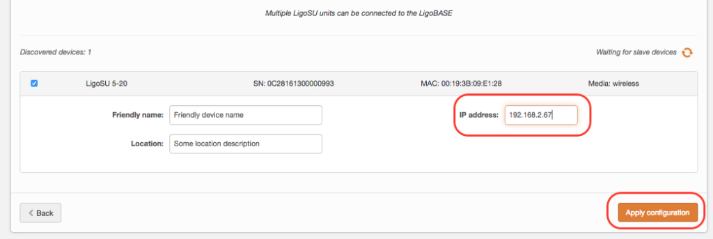
Click Apply configuration and review the LigoPTMP link’s assigned settings:
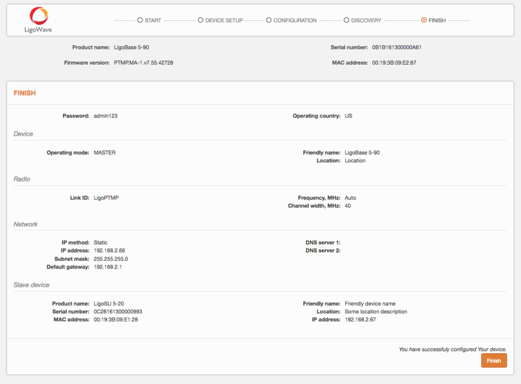
Click Finish to enable and apply the newly assigned settings to both units of the LigoPTMP link.
The LigoPTMP link is now successfully configured.
Check the parameters of the established link on the LigoBASE unit at Status > Information:
Manual Point-to-MultiPoint (PTMP) Link Setup
Follow these steps when connecting to the LigoPTMP Web Management Interface for the first time:
Step 1. Launch the web browser.
Step 2. Enter the device’s default IP address 192.168.2.66 in the browser’s URL field.
Step 3. The LigoPTMP unit should load the user agreement page by default (out of the box or if reset to default settings).
Step 4. Once the user agreement is signed, select the LigoPTMP’s country of operation. Regulatory domain settings may differ depending on the selected country. Users will not be allowed to select radio channels and radio frequency output power outside of the values permitted by the regulatory domain of the selected country.
Antenna gain should be set for products with external antenna only.
Step 5. Once the country is selected, click Next to start the LigoPTMP unit’s installation:
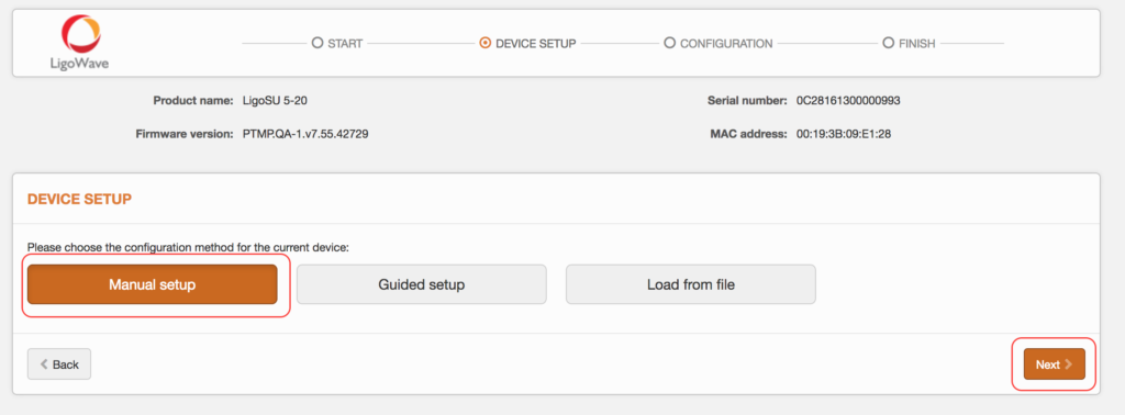
Manual LigoBASE Setup
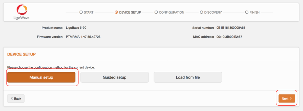
Click Manual setup and Next to start the installation of the LigoPTMP unit:
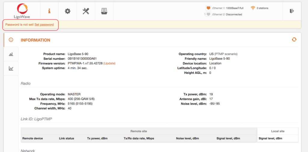
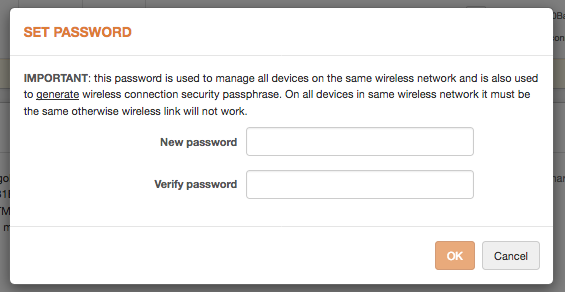
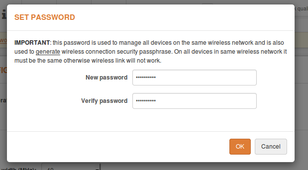
First of all, the user will have to set the password by clicking Set password at the top-left corner of the GUI. Note that by setting the password, the user creates a password for both the security of the connection between LigoPTMP units and the Web Management Interface.
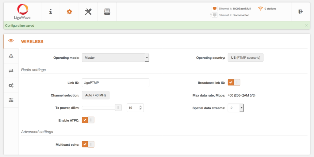
Once the password is set, assign the following parameters: Link ID, Channel selection, and Tx power:
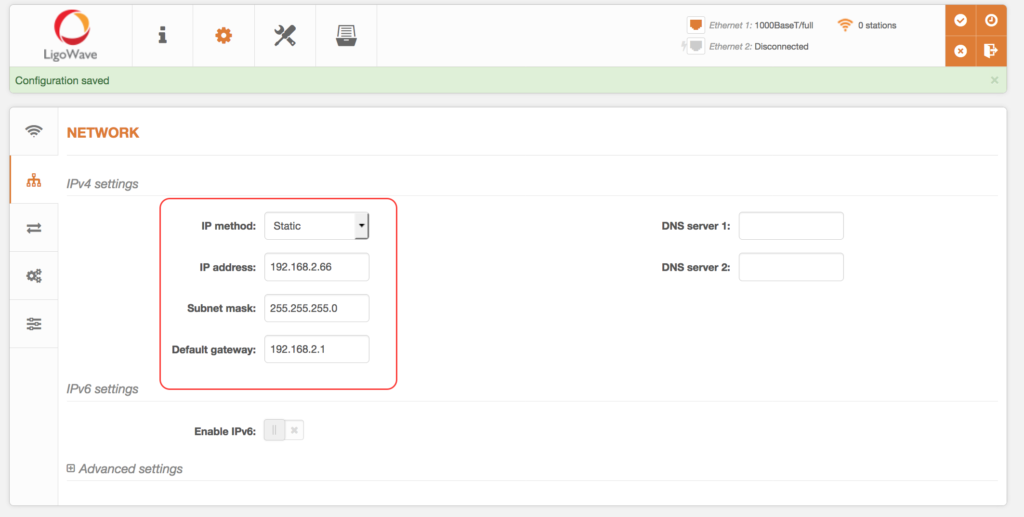
Configure the IP address settings in the Network section:
Click Create next to New slave device config to set up and download the new configuration file for the Slave unit:
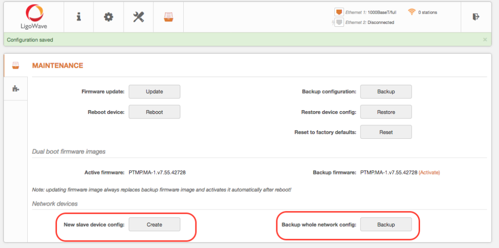
Users can also create a backup config of the entire network.
Once Create is clicked, a dialog window will appear, showing some of the Slave configuration parameters. Indicate the Slave’s IP address and other necessary information.
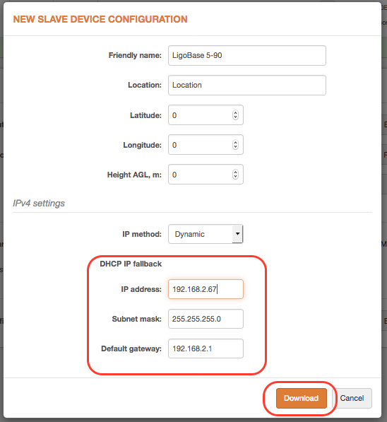
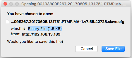
Click Download to receive the newly-created configuration file for the Slave unit.
Connect to the Slave unit. Accept the user agreement, select the Operating country, and click Next.
Then click Guided setup and Next to start the installation of the LigoSU unit:
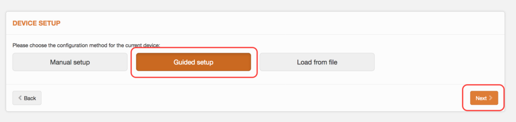
Click Load from file and then click Browse to select the created configuration file:
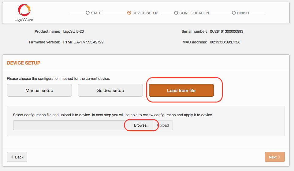
Once the configuration file is successfully uploaded and validated, click Next to finish the configuration.
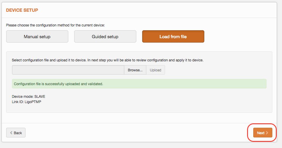
Click Apply configuration.
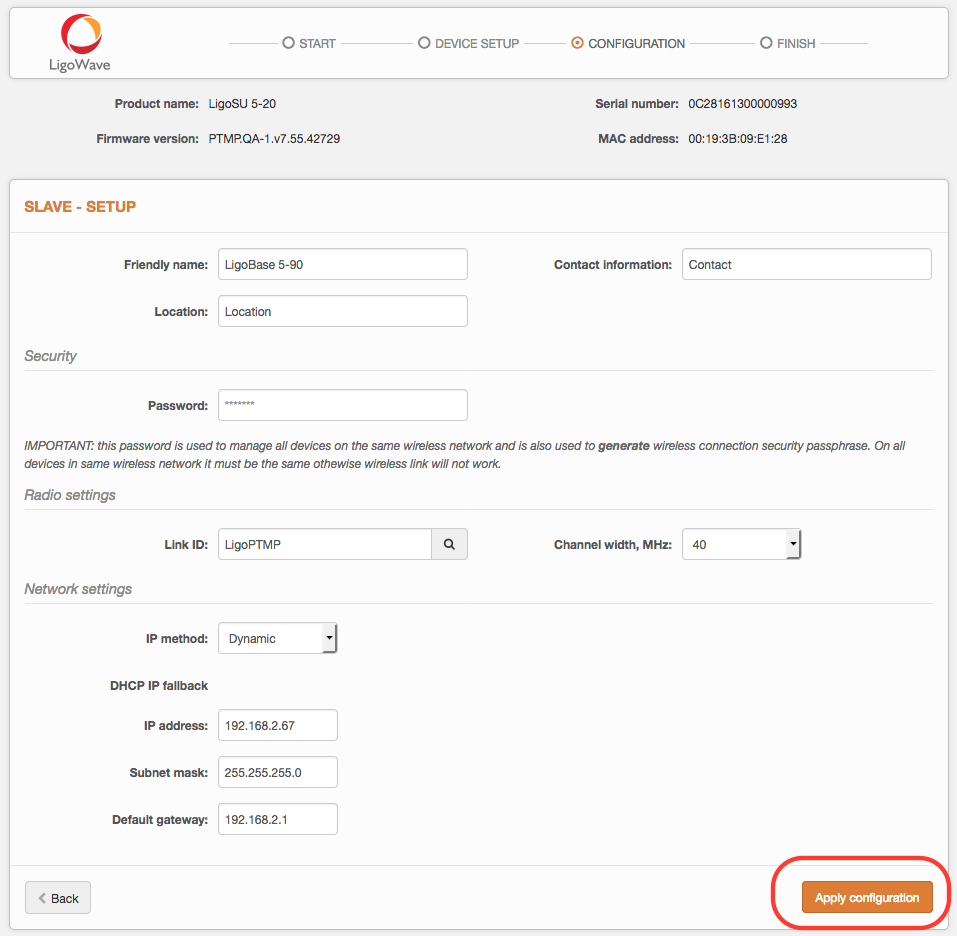
Review the LigoPTMP link’s assigned settings and click Finish to enable and apply the newly-assigned settings to the Slave unit of the LigoPTMP link.
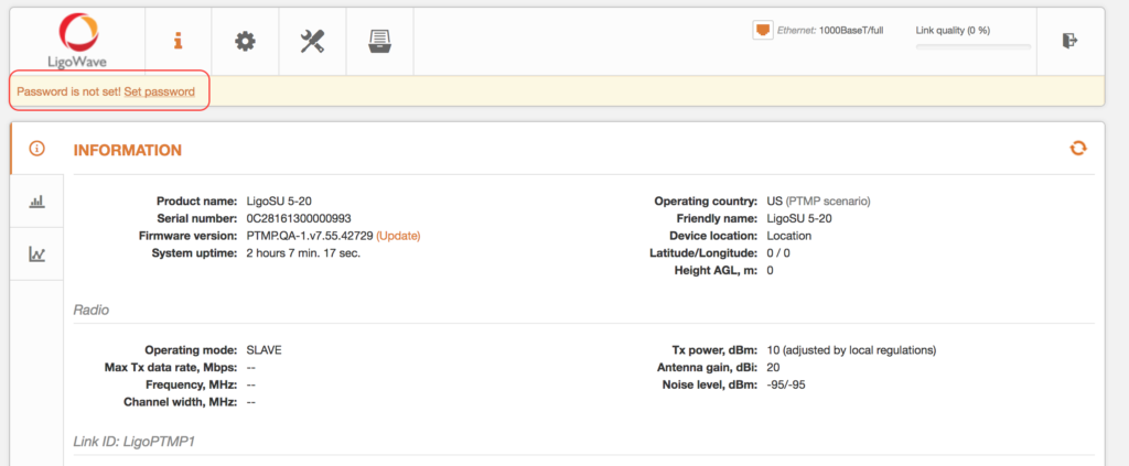
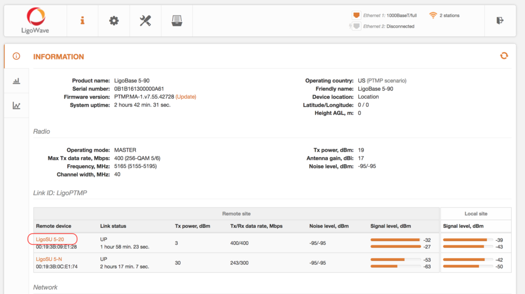
Users can see the parameters of the established LigoPTMP link at Status > Information:
Manual Slave Device Configuration
Connect to the LigoSU unit, accept the user agreement, select the Operating country, and click Next.
In the Device setup section, click Manual setup and Next to begin the installation of the LigoPTMP unit.
First of all, the user will have to set the password by clicking Set password at the top-left corner of the GUI. Note that by setting the password, the user creates a password for both the security of the connection between LigoPTMP units and the Web Management Interface.
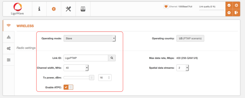
Set the Operating mode to Slave and assign the following parameters: Link ID, Channel width, and Tx power:
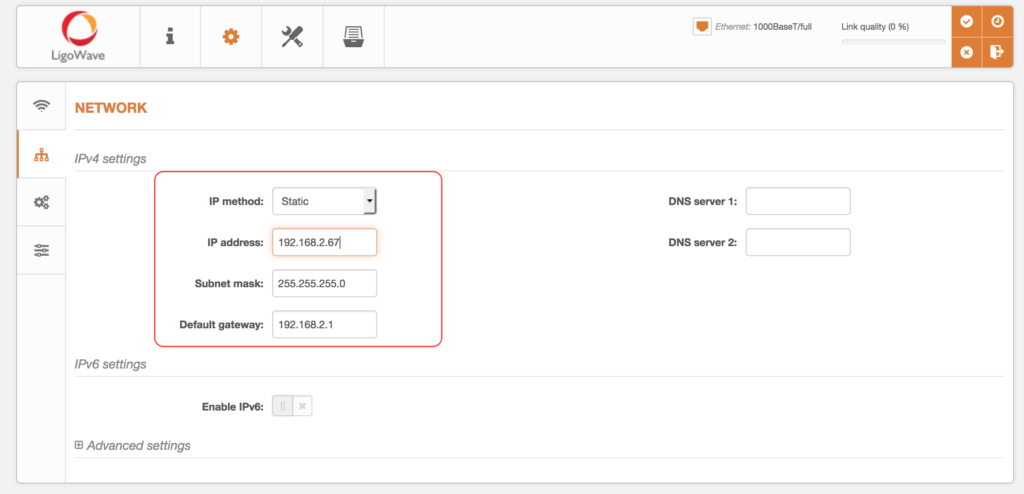
Configure the IP address settings in the Network section:
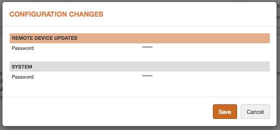
Review the configuration changes and click Save to store the configuration:
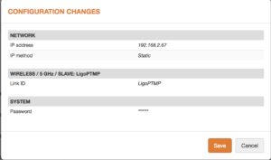
Users can see the parameters of the established LigoPTMP link at Status > Information:
Remote Slave Device Configuration
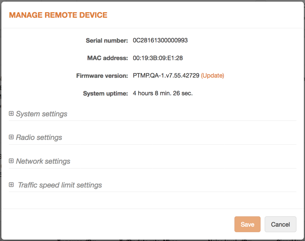
LigoBASE units operate as Master devices. The list of links allows users to manage remote device configurations (Slave devices). Click on an active link (remote device Friendly name) to bring up a dialog box containing the Slave’s settings.
There are 4 main Slave device configuration sections that can be managed from the Master unit:
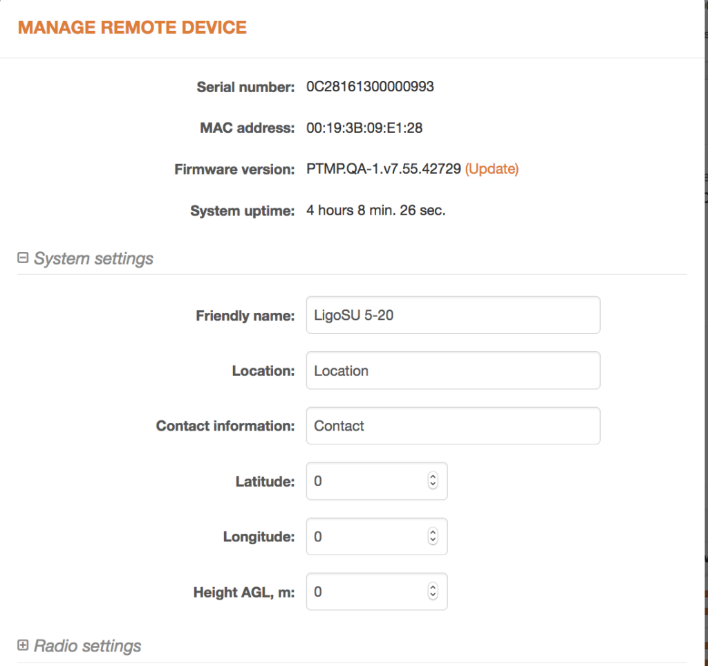
System settings configuration section:
Radio settings, Network settings, and Traffic speed limit settings configuration sections:
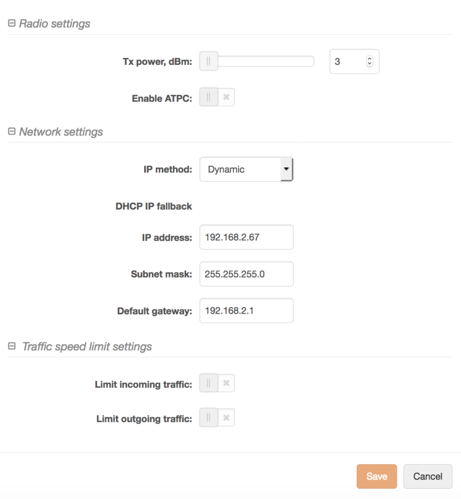
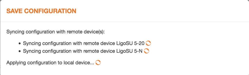
Once the configuration is finished, click Save. The Slave device will be automatically configured without any logins.
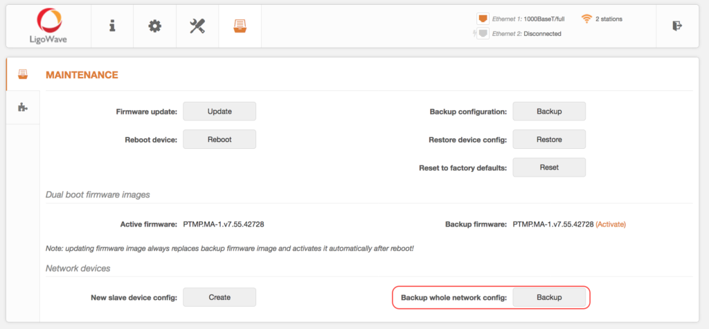
The LigoPTMP Master device has the option to back up the configuration of the entire network.
Click Backup next to Backup whole network config to download the configuration files of the entire LigoPTMP link. The downloaded file will contain two configurations—the Master’s and the Slave’s.
Master Device Configuration Restoration
Begin with the restoration of the Master device configuration:
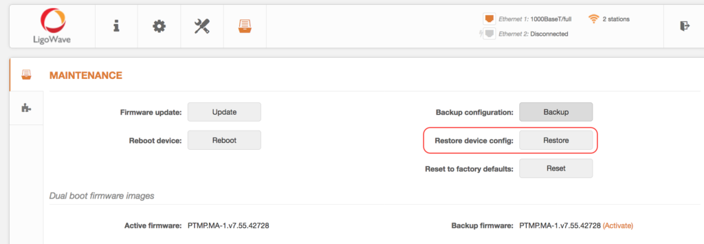
Click Restore next to Restore device config to upload an existing configuration file to the LigoPTMP unit. If the unit is operating as the Master device, then the user can also restore the Slave’s configuration.
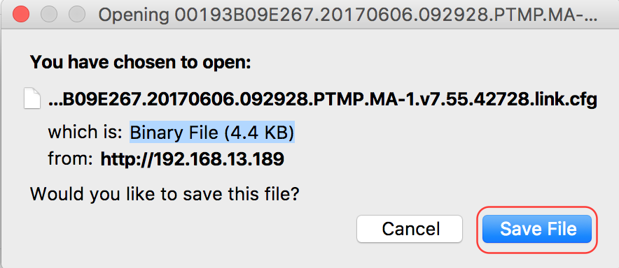
Once the new configuration file is uploaded, click the pop-up to save it:

Review changes and click Save to store the configuration:
Slave Device Configuration Restoration
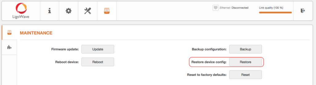
Continue to the restoration of the Slave device configuration. Under Maintenance, click Restore next to Restore device config:
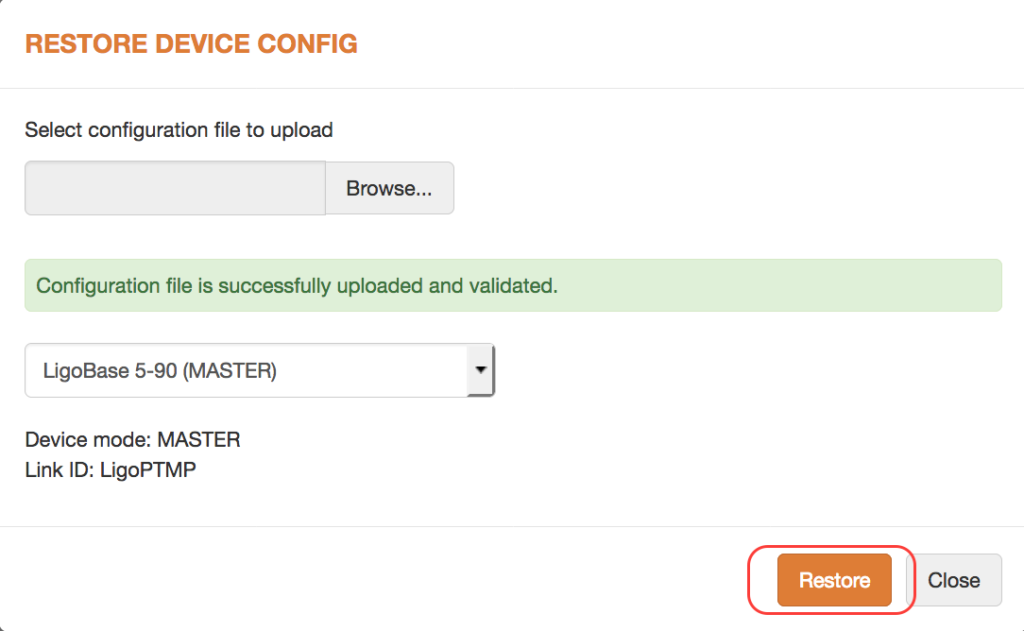
In the Restore device config window, click Browse to select and upload an existing configuration file to the LigoPTMP unit. Afterwards, select the Slave device:
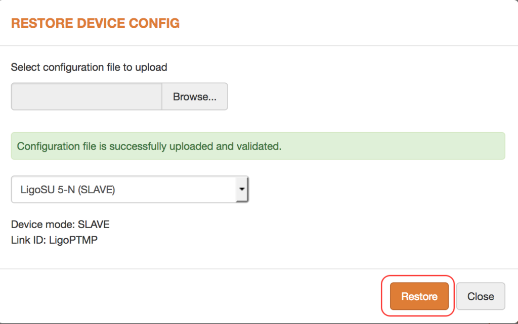
Once the new configuration file is uploaded, click the pop-up to save it:

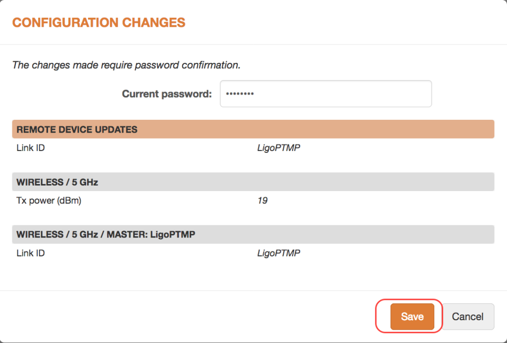
Review changes and click Save to store the configuration:
