If a link is not working well, there are a couple of things that users can try to solve the issue:
Solution #1. Try reducing the Channel Width. The LigoPTMP series of devices have several options to choose from: 5, 10, 20, 40, and 80MHz.
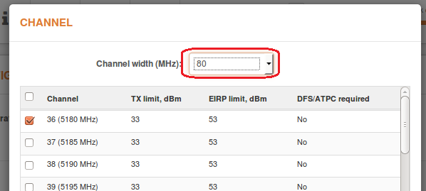
All of the above can be done by navigating to Settings > Radio > Channel selection on the Master device.
Solution #2. If reducing the channel width does not help, the problem may be that there are too many other access points (APs) on the current channel.
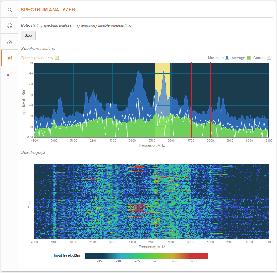
To look for a better channel, navigate to Tools > Spectrum Analyzer. Then click the Start button and wait for 20–30 seconds while the radio gathers enough packets to present real-time noise.

If the current channel coincides with a high peak in the graph, as shown above, it means that there is a lot of noise. Look for a frequency range where noise levels are the lowest. In the example below, ranges with lower noise levels are 5,300–5,380MHz and 5,700–5,780MHz.
To find the right channel and to avoid collision with other APs, perform a scan in Tools > Site survey.
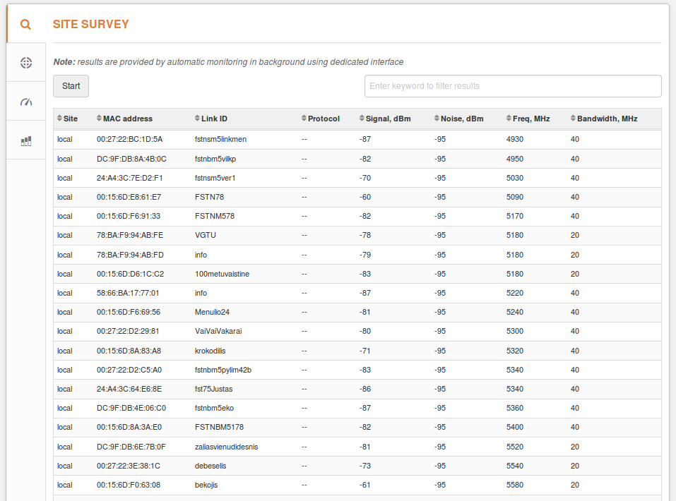
Choose a frequency that does not coincide with a frequency in the Site Survey’s Frequency column and which would be in a clean frequency range. Then, set it to operate as a Master device (Settings > Radio). Moreover, try to avoid frequencies with other devices operating on adjacent frequencies.
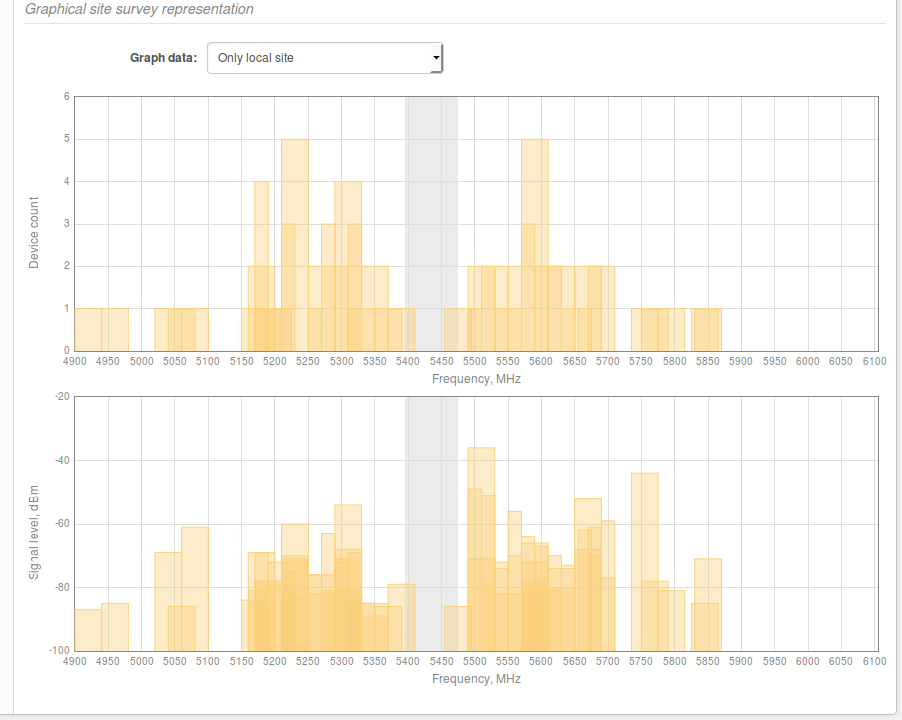
For example, the figure above shows that the 5,430MHz frequency does not have any devices working on it. However, there are nearby devices that are operating on the 5,300MHz and 5,500MHz frequencies, which might interfere with the user’s transmission, especially if the plan is to use an 80MHz channel width.
Once the link is established, use the Link Test speed tool to verify the Tx/Rx data rates and the total capacity of the link. If the results are not good enough, try another channel or reduce channel width. If the speed is sufficiently good, try to shift the current frequency up or down by 5MHz and check whether the throughput is greater.
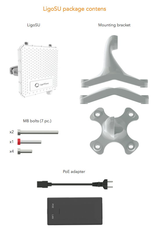
Installation
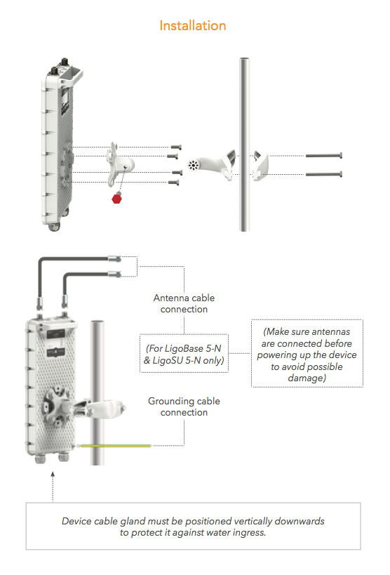
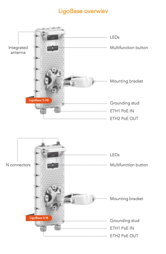
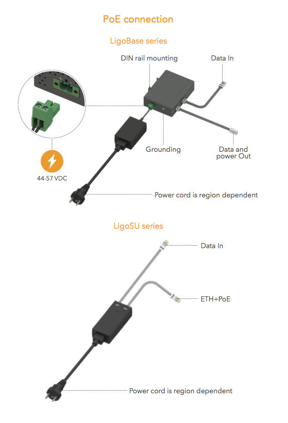
Proper grounding has to be ensured using the grounding stud found on the housing and the PoE inserter.
Recommended cables for use:
- length of cable connecting the switch and the LigoPTMP device, <100m;
- use FTP cable outside;
- use shielded RJ45 plugs outside;
- it is recommended to solder the drain wire to the RJ45 plug;
- use UTP or FTP cable inside.
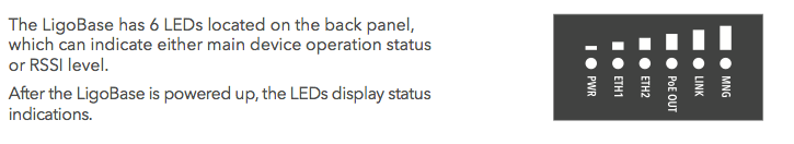
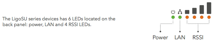
The new model LEDs represent various device operations: boot-up, reset to default settings, reboot, firmware flashing, recovery mode in case of failure, and its primary operation—device status and signal levels.
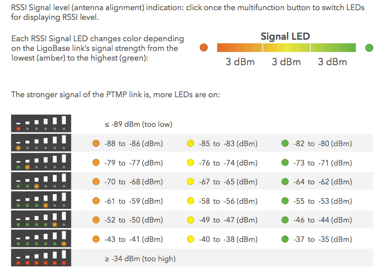
Signal level indication
LEDs are used to indicate signal levels and their changes. The levels are represented using a combination of lights, colors, and brightness: [1] lighting up 1 through 6 LED lights, [2] lighting them up using three distinct colors—amber, yellow, and green, and [3] setting different LED brightness levels—low, middle, and high.
When the signal level changes from low to high, LED1 lights up in amber, starting with low brightness and shifting into high brightness. Afterwards, the brightness cycle repeats when the colors change to yellow and then to green. Once one LED reaches the green state, LED2 lights up in amber at low brightness and proceeds to green at high brightness.
Refer to the graph below for a visual example.
Booting Up
When the device is booting up, each LED represents a phase of the booting process. Starting with LED1, each LED turns on gradually until all of the 6 LEDs are on. Green LEDs signify a successful boot-up.
If any of the booting and startup phases fail, the LED representing that phase will light up in red. LED1–LED3 represent the bootloader, while LED4–LED6 represent kernel.
If all of the phases are successful, the LEDs turn off and perform their primary operation—signal level indication. If any of the phases fail, the LED remains turned on in that state until the problem is resolved.
Firmware Upgrade / Reboot / Reset to Default Settings
If a firmware upgrade, device reboot, or reset to defaults is being performed, blue LEDs light up and move in a snake pattern. The snake’s length is 6 LEDs. It moves from left to right and vice-versa every 100ms.
Recovery Mode
If the device enters the recovery mode (rare case), all of the LEDs begin blinking in red and yellow every 0.5 second.
Operation on GUI
The LEDs can be configured over the GUI:
- Always off: LED indications will be permanently disabled.
- Always on: LED indications will be permanently enabled.
- Auto off: LED indications will be disabled after a specified timeout.
Firmware Upgrade, Reboot, Reset to Default Settings
If a firmware upgrade, device reboot, or reset to defaults is being performed, blue LEDs light up and move in a snake pattern. The snake’s length is 6 LEDs. It moves from left to right and vice versa every 100ms.
Recovery Mode
If the device enters the recovery mode (rare case), all of the LEDs begin blinking in red and yellow every 0.5 second.
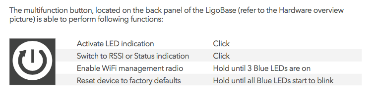
Reset Button
The reset button has 4 functions:
- Reset to default settings.
Press and hold the reset button for 6 seconds until all of the LEDs turn on and begin blinking. When the reset button is pressed, the LEDs will start to gradually light up—one light every second—from LED1 through LED6. Afterwards, the LEDs start blinking every 0.5 seconds, which means that the reset button can be released. This process will reset the device to its default settings. - Wake up the Wi-Fi management radio.
The Wi-Fi management radio’s period of activity has a time limit, which means that the radio turns off after a certain amount of time. Press and hold the reset button for 2–4 seconds until 2–4 LEDs light up. This will wake up the device. This works, if the radio is not disabled via the GUI. - Activate the LEDs after a timeout.
Press and hold the reset button for 1 second. - Switch between LED main operating mode 1 and 2
Press and hold the reset button for 1–2 seconds to switch between the signal indication mode (mode 1) and the device state indication (mode 2).
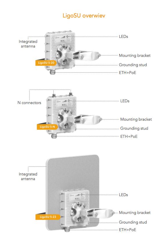
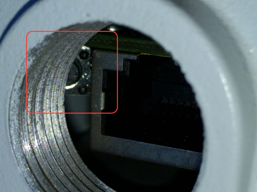
All LigoSU units have a reset button near the Ethernet port as shown in the image below. To reset the device, press and hold the reset button for 5 seconds and then release it. The process of resetting the device starts when the device’s LEDs begin blinking.
The Antenna Alignment Tool measures the signal quality between the Master and Slave devices. To achieve the best results when aligning antennas, turn off all wireless networking devices within range of the device, except the device (or devices) with which you are trying to align the antenna. Watch the display for real-time feedback as you adjust the antenna.
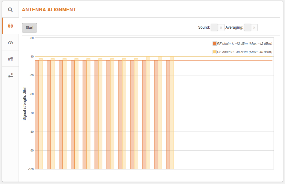
Start/Stop – press to start or to stop antenna alignment.
Averaging – if enabled, the graph will display the average signal strength of both vertical and horizontal polarities.
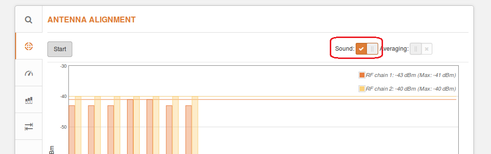
Sound – if enabled, sound (beeps) will be produced during alignment (if the browser allows this).
Proper Antenna Alignment
1. Disable ATPC functionality.
2. Set the maximum Tx power.
3. Choose the compliance testing country code during installation.
Once alignment is completed, choose your country code and enable ATPC functionality.
LigoPTMP devices can be mounted on poles. The minimum and maximum diameters are provided bellow:
| Product | Compatible pole diameter, cm | |
| minimum, cm | maximum, cm | |
| LigoBASE |
3 | 11 |
| LigoSU | 3 | 11 |