PTP Link Configuration
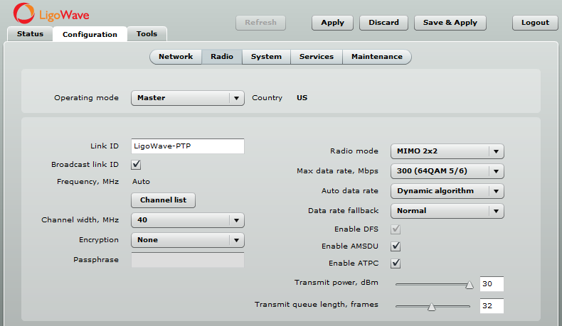
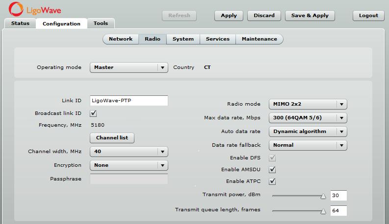
Master Device Configuration
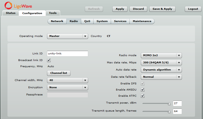
- select your country code;
- indicate the link ID;
- choose the least occupied frequency (for instructions on how to choose the best operating channel, see Improving Link Stability and Throughput in Noisy Environments under LigoPTP RapidFire Installation Recommendations);
- select channel width;
- if necessary, enable encryption;
- leave all of the other settings as their default values.
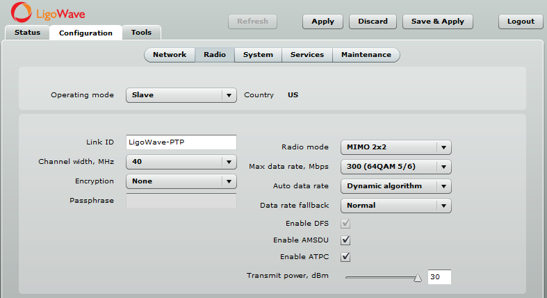
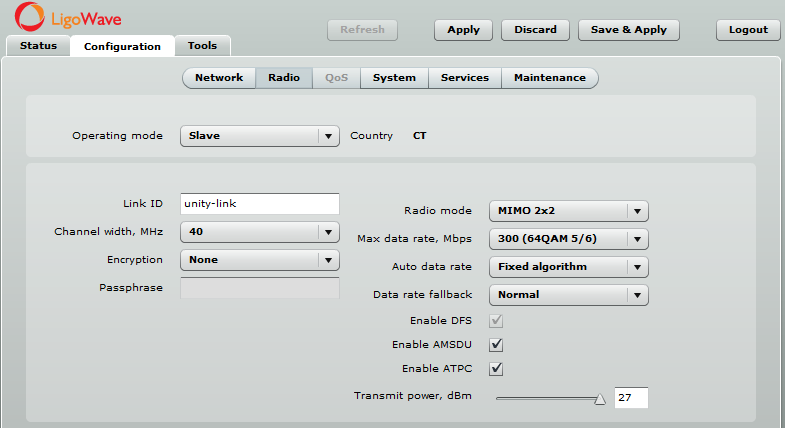
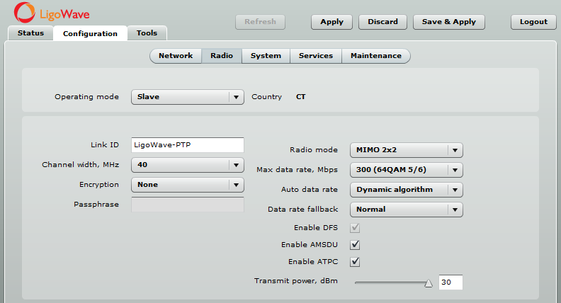
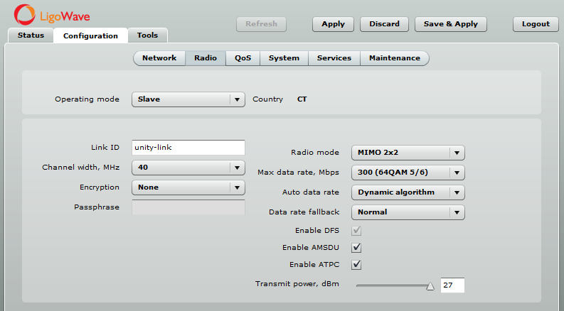
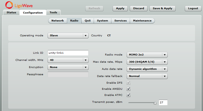
Slave Device Configuration

- select the country code;
- indicate the link ID;
- choose the channel width;
- if necessary, enable encryption;
- leave all of the other settings as their default values.
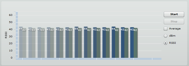
Check Signal Levels
- Local signal – received signal strength from a remote PTP (Master device in this case).
- Remote signal – received signal strength from a local PTP (Slave device in this case).
- Two signal bars mean two streams – 2 transmit/2 receive (MIMO).
Antenna Alignment
- If necessary, perform antenna alignment.
- RSSI is a positive value because it is calculated by subtracting the signal level from the noise level.
- A higher positive RSSI value is better.
- RSSI evaluates signal level and environment noise.
- RSSI should differ on the chain by only a few units.
PTP Link Configuration
Master Device Configuration
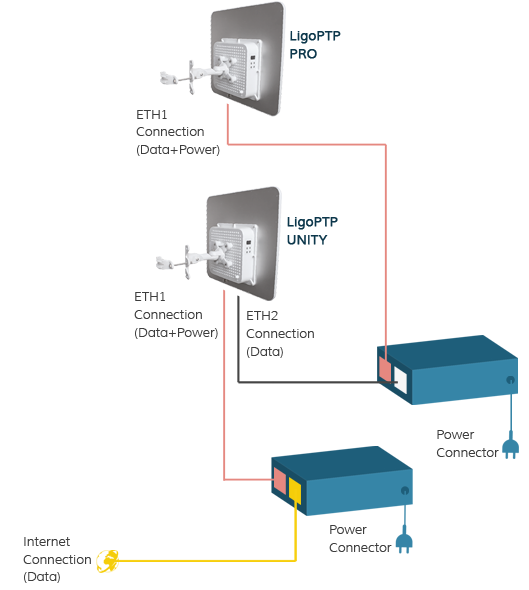
Configure one PTP Unity device to function as the Master device. Assign a unique Link ID, run the Site Survey tool, and select a frequency that is not crowded. For instructions on how to choose the best operating channel, see Improving Link Stability and Throughput in Noisy Environments under LigoPTP RapidFire Installation Recommendations.
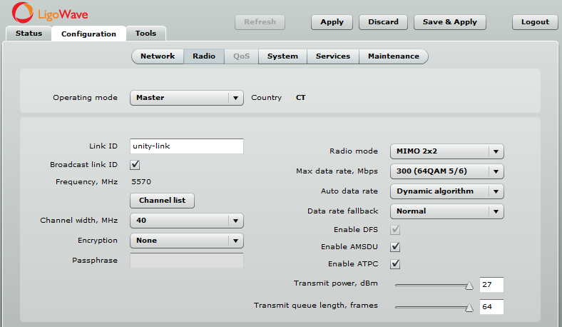
Configure one PTP PRO device to function as the Master device. Assign a unique Link ID (different from the one used for Unity), run the Site Survey tool, and select a frequency that is not crowded.
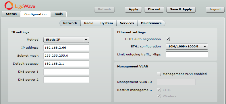
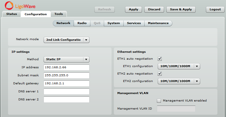
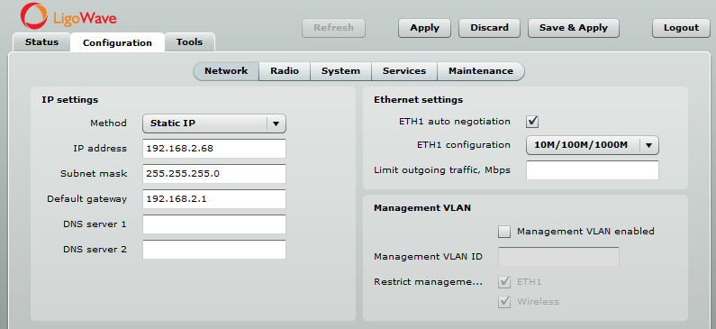
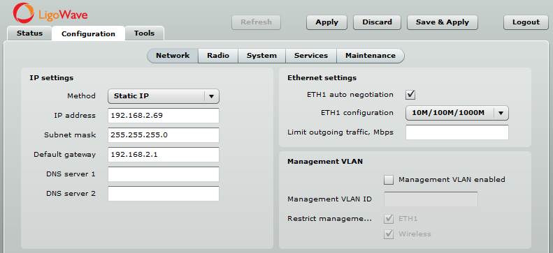
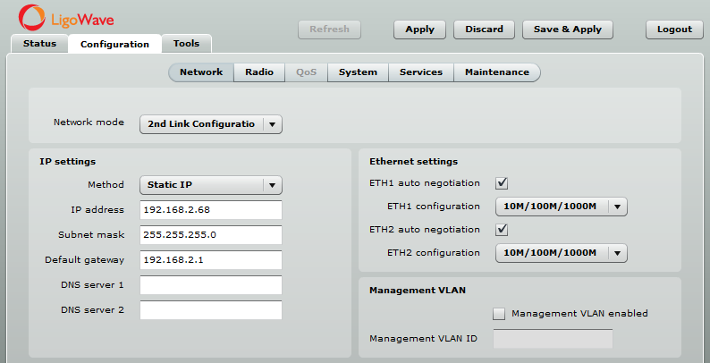
Change the IP address of the PTP PRO Master device to 192.168.2.68 (as shown in the example):
Slave Device Configuration
Configure the second PTP Unity device to function as the Slave device. Enter the same Link ID as on the Master device.
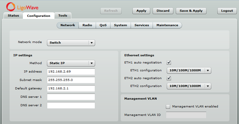
Change the IP address of the PTP PRO Slave device to 192.168.2.69 (as shown in the example):
Configure the second PTP PRO device to function as the Slave device. Enter the same Link ID as on the Master device.
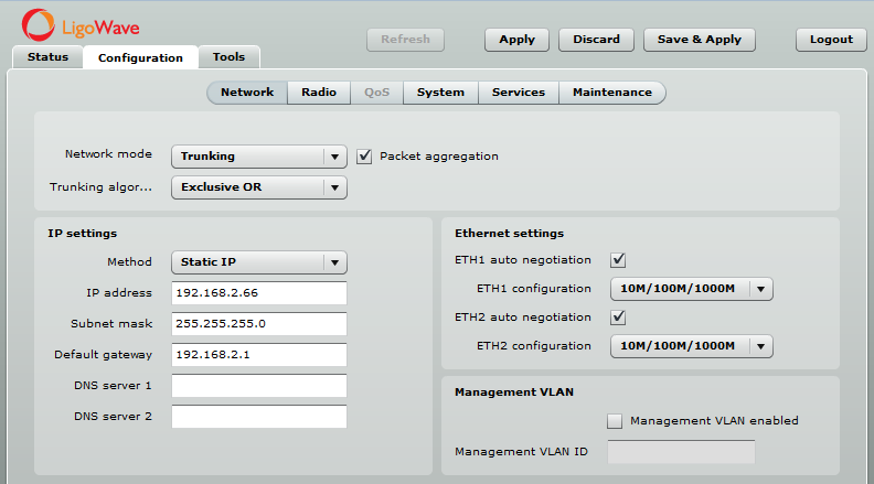
Aggregation Mode Configuration
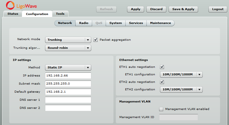
First of all, change the Network mode on the Unity Slave device from 2nd Link Configuration to Trunking with Packet aggregation enabled and the Trunking algorithm set to Round-robin.
Then change the Network mode on the Unity Master device from 2nd Link Configuration to Trunking with Packet aggregation enabled and the Trunking algorithm set to Round-robin.
Run Linktest to check link throughput in aggregation mode.
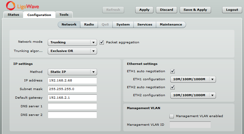
If Windows machines are mostly used throughout the network, it is recommended to use the Exclusive OR trunking algorithm.
Unity Slave Configuration:
Unity Master Configuration:
PTP Link Configuration
Master Device Configuration
Configure one PTP Unity device to function as the Master device. Assign a unique Link ID, run the Site Survey tool, and select a frequency that is not crowded. For instructions on how to choose the best operating channel, see Improving Link Stability and Throughput in Noisy Environments under LigoPTP RapidFire Installation Recommendations.
Configure the second PTP Unity device to function as the Master device. Assign a unique Link ID (different from the one used for Unity), run the Site Survey tool, and select a frequency that is not crowded.
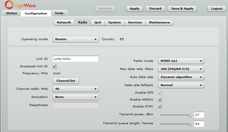
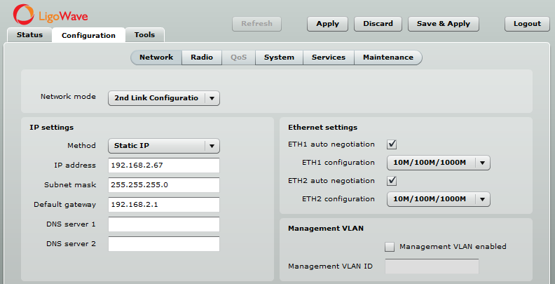
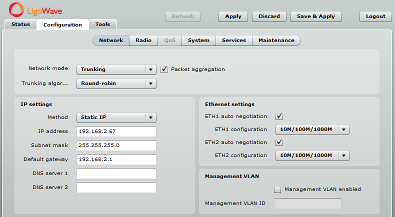
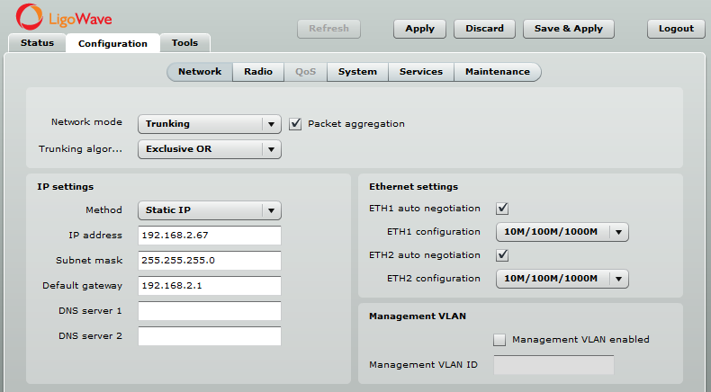
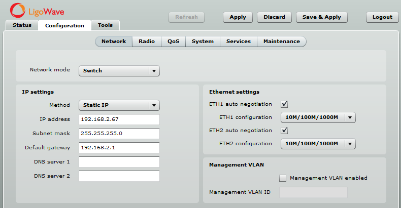
Change the IP address of the Second PTP Unity Master device to 192.168.2.67 (as shown in the example) and set the Network mode to Switch:
Slave Device Configuration
Main Unity Slave Device Configuration:
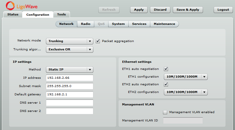
Change the IP address of the Main PTP Unity Slave device to 192.168.2.68 (as shown in the example):
Second Unity Slave Device Configuration:
Configure the second PTP Unity device to function as the Slave device. Enter the same Link ID as on the Master device.
Change the IP address of the Second PTP Unity Slave device to 192.168.2.69 (as shown in the example) and set the Network mode to Switch:
Aggregation Mode Configuration
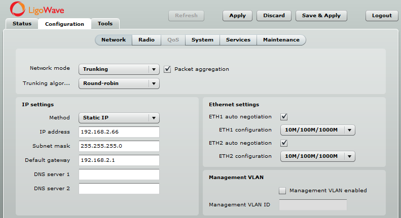
First of all, change the Network mode on the Main Unity Slave device from 2nd Link Configuration to Trunking with Packet aggregation enabled and the Trunking algorithm set to Round-robin.

Then change the Network mode on the Main Unity Master device from 2nd Link Configuration to Trunking with Packet aggregation enabled and the Trunking algorithm set to Round-robin.
Run Linktest to check link throughput in aggregation mode.
If Windows machines are mostly used throughout the network, it is recommended to use the Exclusive OR trunking algorithm.
Main Unity Slave Configuration:
Main Unity Master Configuration: