There are several solutions that users can implement, if a link is not working well.
1. Set the Channel width to the lowest available value.
2. Gradually reduce the Max data rate one step at a time (from 300 to 240, then to 180, etc.).
3. Make sure that Dynamic rate is enabled.
4. Set Transmit queue length to 32.
The aforementioned changes can be performed in Configuration > Radio on the Master device.
If these solutions do not fix the problem, the problem may lie in the fact that the current channel has too many other Access Points (APs). To look for a better channel, navigate to Tools > Spectrum Analyzer and click Start. Wait 20–30 seconds while the radio gathers enough packets to provide real time noise data.
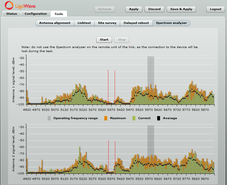
If the device’s current operating channel is overcrowded, as shown by the high noise bars in the above picture, look for a frequency range where noise bars are the lowest. The above example shows that the frequency ranges with the least amount of noise are 5,340–5,380MHz and 5,430–5,470MHz.
To find the right channel and to avoid collision with other APs, perform a scan in Tools > Site survey.
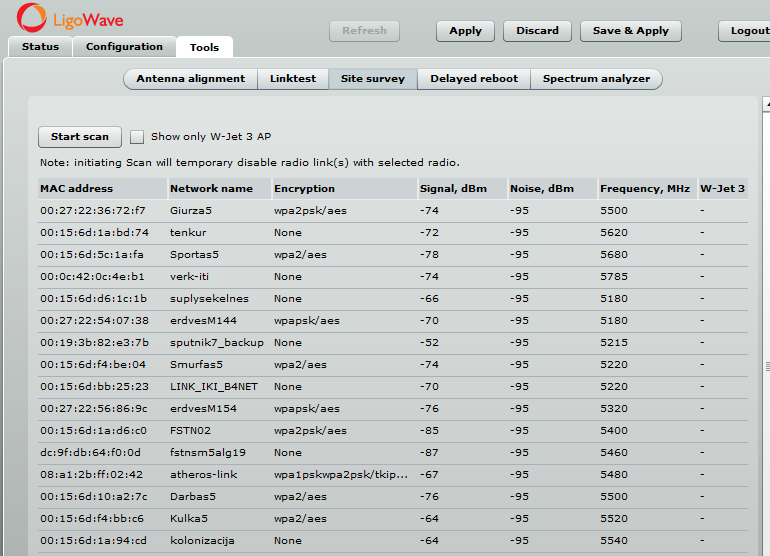
Choose a frequency that does not match the frequency indicated in the Site Survey’s Frequency column and which is within a clean frequency range. Then set it up on the Master device (Configuration > Radio).
Also, try to avoid frequencies with other devices working on adjacent frequencies. For example, the illustration provided above shows that the 5,430MHz frequency does not have any devices operating on it. However, there are devices operating nearby on 5,400MHz and 5,460MHz, which can cause interference, especially of the idea is to use 40MHz channels.
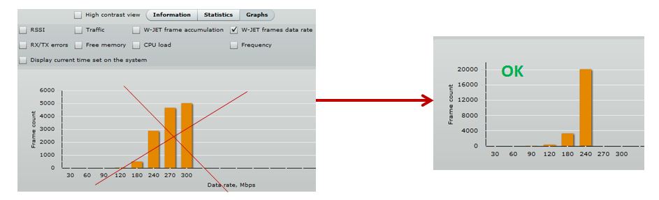
Once a link is set up, use the LinkTest tool to verify the W-Jet frames data rate and the overall capacity of the link. If the results are not good enough, try another channel or decrease the maximum data rate. If the speed is sufficiently good, try to move the current frequency up or down by 5MHz and check if throughput improves even more.
Link Installation Recommendations
Link aggregation configuration can be found here.
Follow these rules to achieve maximum performance using link aggregation:
1. If the devices are using integrated antennas, mount the devices at least 2 meters apart from each other. The farther—the better.
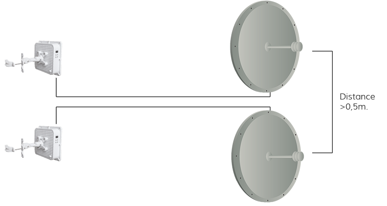
2. If the devices are using dish antennas, mount the dishes at least 0.5 meters apart from each other. The farther—the better.
3. Use different channels on Unity and PRO devices. Channels should be separated by at least 100MHz. Ideally—300MHz.
LigoPTP Unity + PRO Mounting Recommendations
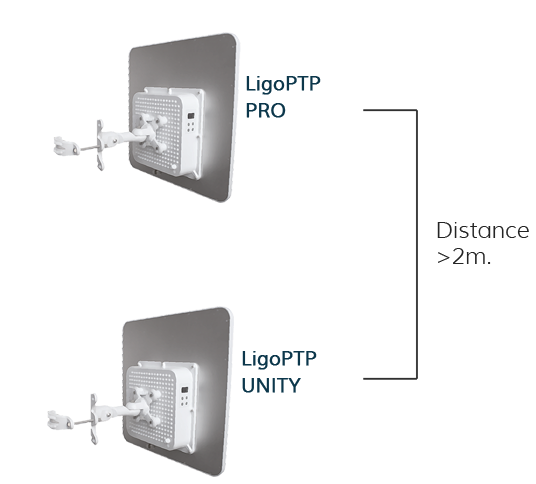
Mounting Recommendations for LigoPTP Unity + PRO with External Antennas
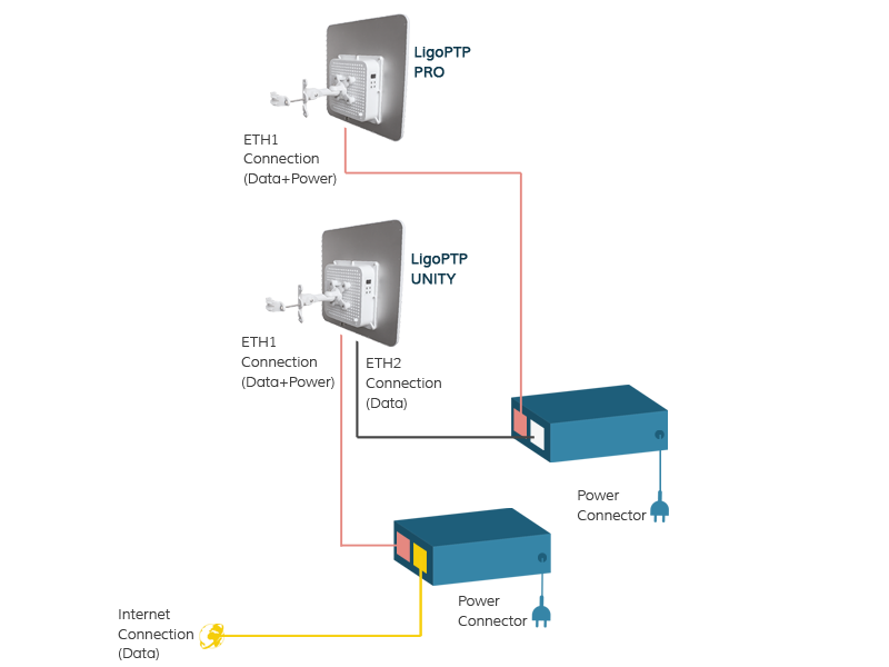
Standard LigoPTP Unity + PRO Setup
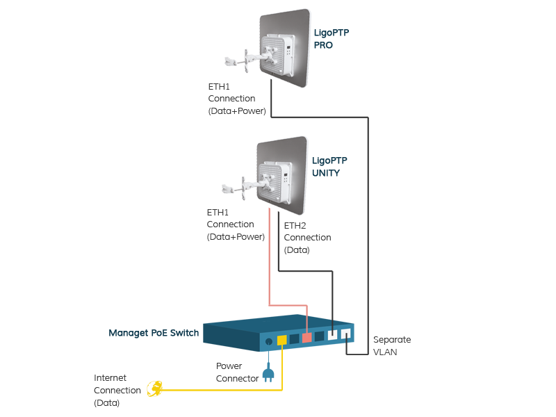
LigoPTP Unity + PRO Setup Using PoE Switches
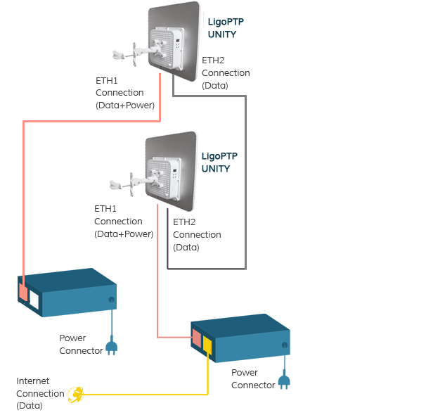
LigoPTP Unity + Unity Setup Scheme