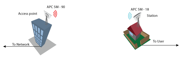
Perform the following steps to create a simple Point-to-Point link between Access Point iPoll and Station (iPoll):
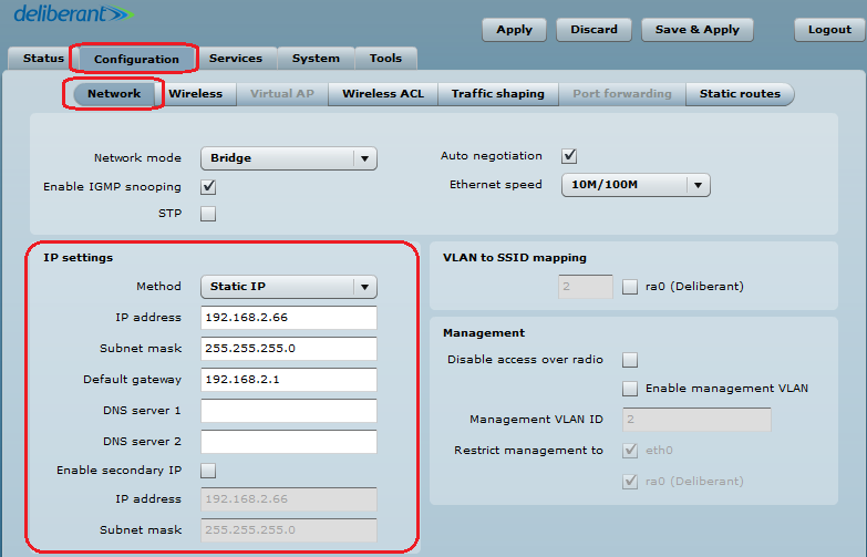
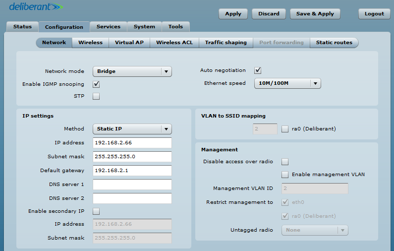
Step 1. Access Point iPoll Configuration. Change the device’s default IP address (can be static or dynamic) and enable IP alias, if necessary:
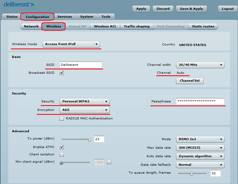
Step 2. Configure the wireless settings for Access Point iPoll:
- set Wireless mode to Access Point iPoll;
- indicate the SSID;
- set Channel to Auto;
- enable Security for secure traffic over the link.
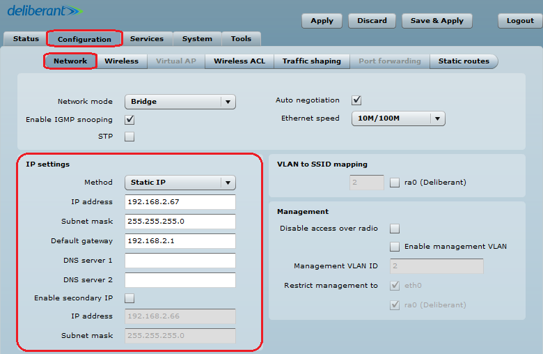
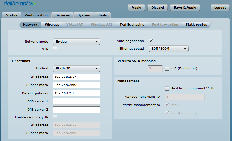
Step 3. Station iPoll Configuration. Change the device’s default IP address (can be static or dynamic) and enable IP alias, if necessary:
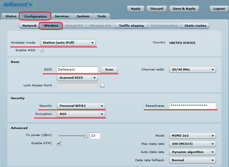
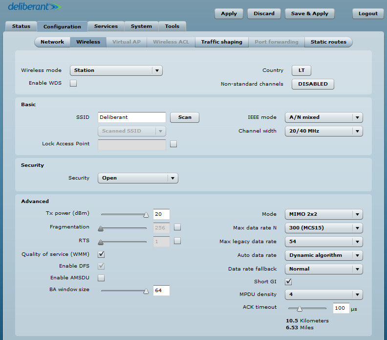
Step 4. Configure the wireless settings for Station iPoll:
- set Wireless mode to Station (auto iPoll);
- indicate the SSID or use Scan to automatically find iPoll Access Points;
- enable Security for secure traffic over link.
All other settings should be left as their default values.
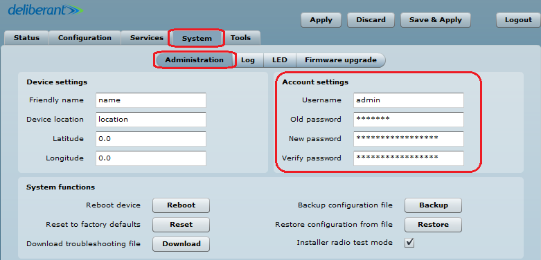
Step 5. It is highly recommended to change the default administrator’s password for each unit:
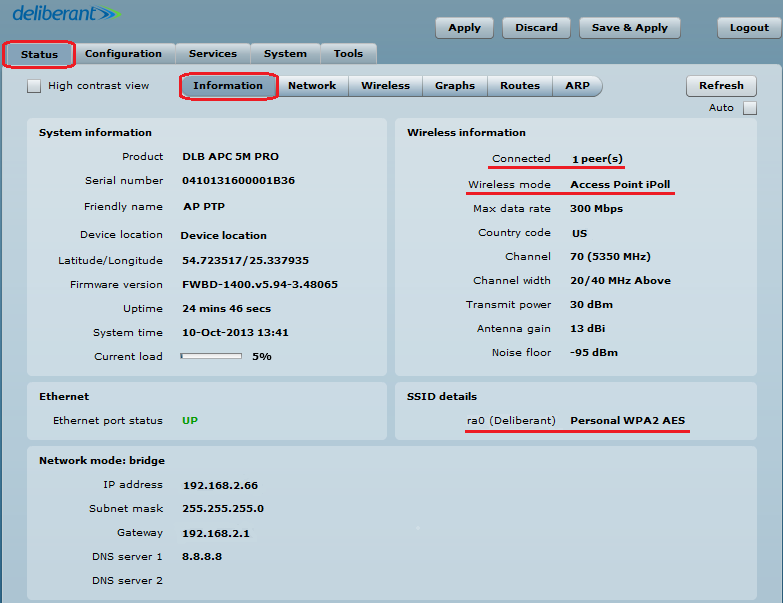
Step 6. Verify the PTP link connection. Navigate to Status > Information. The information page will display data for the wireless link.
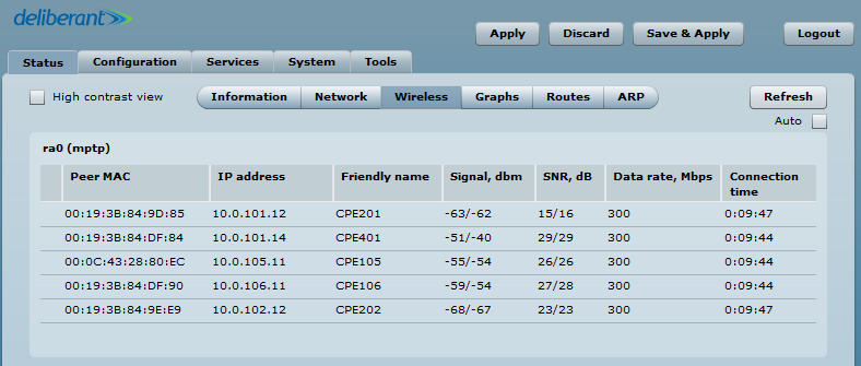
Access Point iPoll’s status page should indicate that one peer (Station iPoll) is connected and should provide information about the connection as follows:
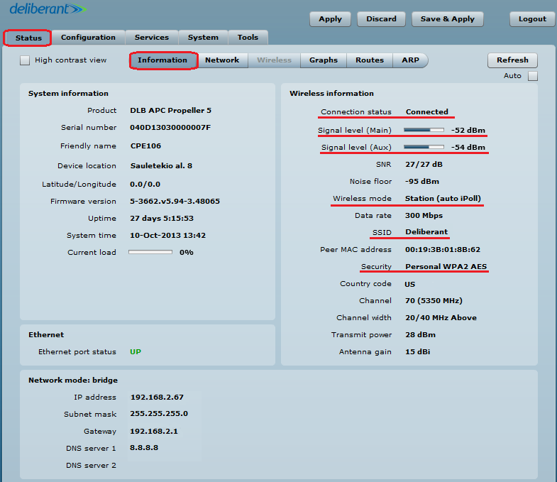
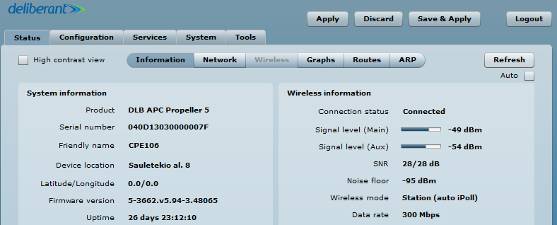
Station iPoll’s status should show up as Connected and there should be progress bars indicating the quality of the connection:
Point-to-Multipoint Bridged Network Configuration
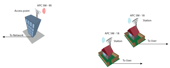
Configuration
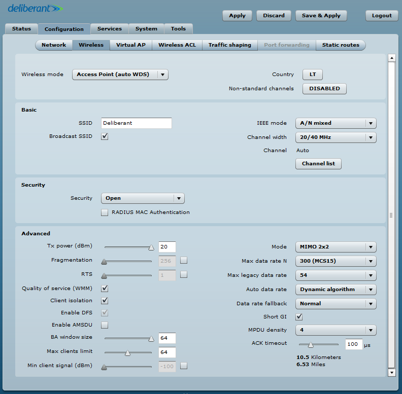
Steps for configuring the Wireless tab on the Access Point:
- select the Country;
- set Wireless mode to Access Point (auto WDS);
- define the SSID;
- choose IEEE mode: use N, if 802.11n-capable radios are used; use A/N mixed or B/G/N mixed, if legacy radios are used on the network;
- set Channel to Auto;
- set Max data rate;
- set Auto data rate to Dynamic algorithm;
- enable Security, if necessary;
- set ACK timeout based on the maximum distance from the station.
Leave all other settings as their default values.
Configuration of the Stations:
Steps for configuring the Wireless tab on the Station:
- select Country;
- set Wireless mode to Station WDS.
Set the following in accordance with the access point:
- indicate the SSID;
- choose the IEEE mode;
- set Max data rate N to Auto;
- enable Security, if necessary;
- set ACK timeout based on the maximum distance from the station.
If the device is MIMO, there are two signal streams. One of them is Main (Antenna 1) and the other is Aux. The Main’s stream is mandatory. If Main’s signal is very weak, the link will not be stable or will not work at all. It is necessary to align the antennas to achieve the best Main signal. If Aux’s stream is weak, the link will work at a lower data rate. Check whether the SNR is good on the AP and the Station and whether it is above 20/20.
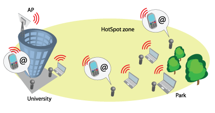
HotSpots are popular in public locations such as airports, shops, bars, or stadiums. The APC allows user authentication using external or internal web portals. This authentication method is called UAM. Users provide login credentials and then the web portal attempts to authenticate and authorize the client using the provided information. The client will not send any authentication requests directly to the APC—the web portal will do that. If successful, the APC will allow access to the Internet. Otherwise, the web portal will display a failure notice.
Follow these steps to configure a Hotspot with UAM authentication using the external web portal for wireless clients:
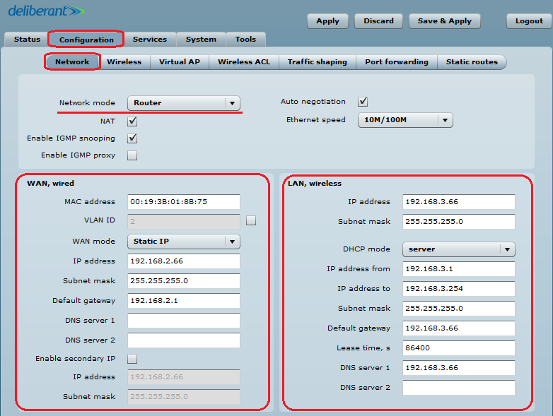
Step 1. Navigate to Configuration > Network and make sure that the APC is operating as a Router. This is the only way a HotSpot will work with UAM authentication.
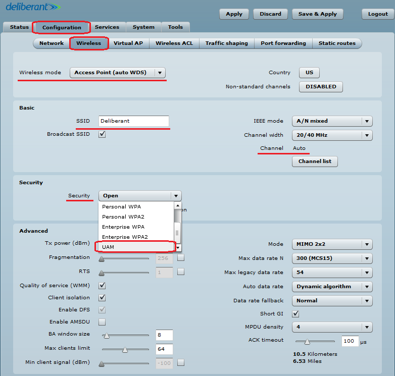
Step 2. Set up the Wireless settings for the HotSpot:
- set Wireless mode to Access Point (auto WDS);
- indicate the SSID;
- set Channel to Auto;
- set Security to UAM.
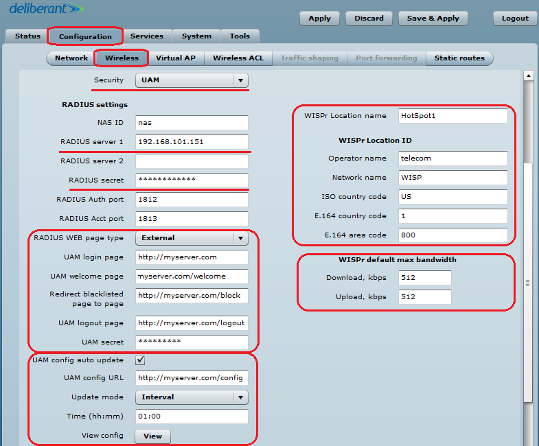
- set up at least one RADIUS server by indicating the IP address, RADIUS secret, and authentication and accounting ports;
- fill out the external UAM fields: login page URL, welcome page URL, blacklist URL, and logout URL;
- UAM configuration can be automatically updated from the server at scheduled times;
- UAM supports a HotSpot description based on WISPr 1.0 recommendations: WISPr location name, operator name, network name, ISO country code, E.164 country code, and E.164 area code;
- UAM supports traffic limitations and has fields for default bandwidth definitions. These parameters and attributes can be overridden per user through RADIUS.
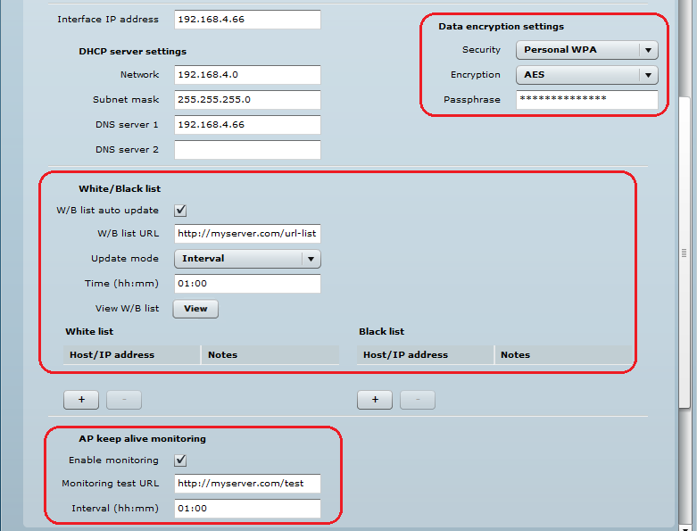
- WPA-PSK encryption can be used on UAM for stronger security;
- UAM supports white/black lists, which can be configured statically on the device or can be updated automatically from the server;
- UAM has an option for AP monitoring through HTTP URL.
Step 5. Once UAM authentication is successfully configured on the APC, all wireless clients will be redirected to the external web portal for authentication.
Virtual AP
Use the Configuration > Virtual AP page to configure and to create up to 7 additional Virtual AP interfaces. The Virtual AP defines a logical wireless network and the APC can be configured to provide additional 7 wireless networks on each device radio. All of the VAPs may be active at the same time, meaning that the client devices can associate to the APC using any of the VAP SSIDs.
The Virtual AP table displays a summary of all virtual radio interfaces running on the APC:
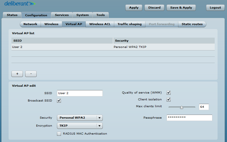
To create a new Virtual AP, click on the Plus Button (+) to add a new entry to the VAP table. Then select this entry and specify the required parameters:
- SSID – specify the unique name for the VAP [string].
- Broadcast SSID – when this option is selected, the particular SSID is visible on a wireless station during network scans. When deselected, the VAP SSID is not visible and not broadcast to wireless stations.
- Quality of Service (WMM) – enable to support Quality of Service for prioritizing traffic.
- Client isolation – enable user layer 2 isolation. The layer 2 isolation blocks wireless clients from communicating with each other.
- Max clients limit – specify the maximum number of associated wireless clients per VAP.
- Each VAP’s security is configured by default as an “open system”, which broadcasts a beacon signal including the configured SSID. For a more secure network, choose one of the security mechanisms for each VAP interface.
- Security – choose the wireless security and encryption method from the drop-down list.
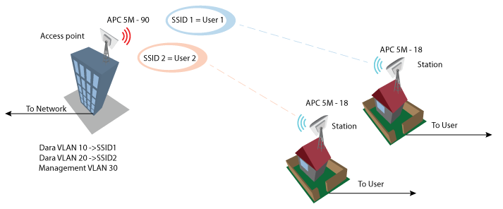
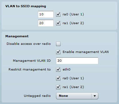
VLAN to SSID Mapping
Virtual Local Area Networks (VLANs) are logical groupings of network resources.
VLAN to SSID mapping – specify the VLAN ID for traffic tagging on the required radio interface [2-4095]. Station devices that associate using the particular SSID will be grouped into this VLAN. The configuration window can be found at Configuration > Network. When the device’s interfaces are configured with a specific VLAN ID value in the management section, the device will only accept management frames that match the configured VLAN ID. The Restrict management function is used when the stations have to be managed via VLAN too.
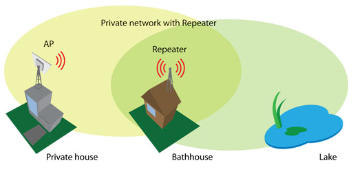
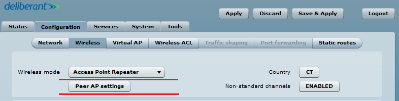
Use the Access Point Repeater mode to extend the range of the existing network infrastructure. The access point repeater’s wireless settings have the possibility to scan the SSIDs of the surrounding APs and to choose the required one. Enable WDS when the main AP is also working in WDS mode. Do not forget to add the security information, which is needed to connect to the main AP. Also, the country codes should be the same on all devices.
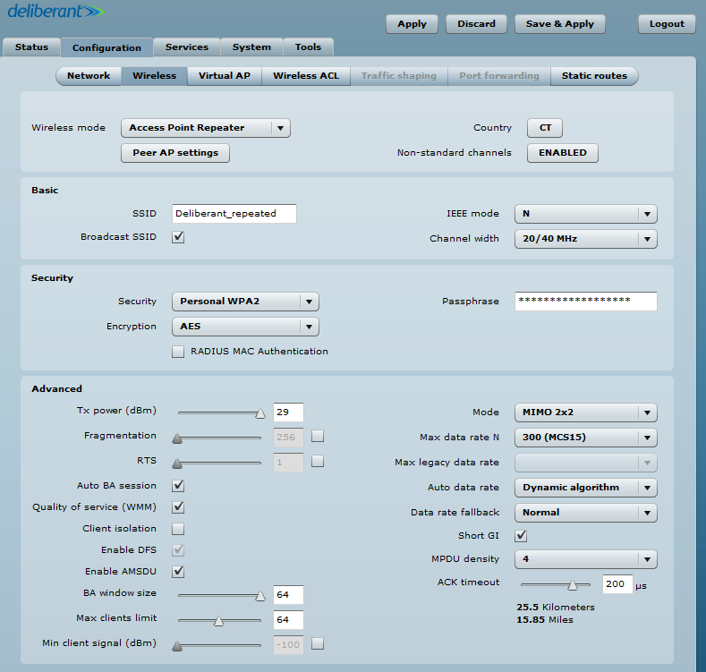
Repeater Basic Wireless Settings
- SSID – specify the SSID of the remote access point.
- Enable/Disable WDS – sets the access point repeater mode to WDS or non-WDS
- Scan – click to scan for surrounding wireless networks. Found network SSID’s will be available in the drop down menu.
- Peer Access Point MAC Address – enter the MAC address of the remote access point.
- Broadcast SSID – enable or disable SSID broadcasting.
- IEEE mode – specify the operating wireless mode.
- Channel width – the default channel bandwidth for 802.11 radios is 20MHz. 802.11n allows channel bonding in such a way that the total channel width becomes 40MHz.
Step 1. Set wireless mode to Access Point Repeater and go into Peer AP settings.
Step 2. Scan and choose the AP SSID that is going to be repeated.
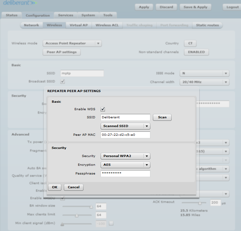
Step 3. The same AP SSID and security information as that of the main one or a completely new SSID can be created in the Basic and Security sections of the window.
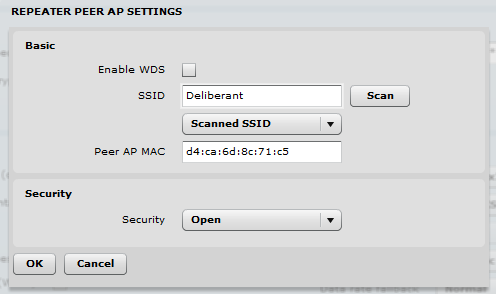
WDS mode should be disabled when the main AP is working in regular non-WDS mode. It is commonly used when trying to repeat a simple wireless router.
Traffic Limiting
Use Traffic Shaping to control the download or upload bandwidth to optimize or guarantee performance. There are two methods for controlling network traffic:
- Limit all traffic – limits overall APC upload and download traffic.
- Limit per IP traffic – limits upload and download traffic for a specified IP addresses.
Limit all traffic
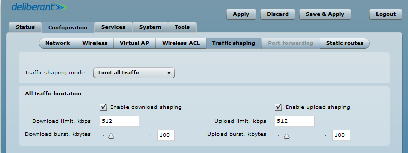
- Enable download shaping – select to enable the limitation of the download traffic.
- Download limit, kbps – specify the maximum download bandwidth value in Kbps.
- Download burst, kbytes – specify the download burst size in kbytes.
- Enable upload shaping – select to enable limitation of the upload traffic.
- Upload limit, kbps – specify the maximum upload bandwidth value in Kbps.
- Upload burst, kbytes – specify the upload burst size in kbytes.
Limit per IP traffic
Use the Plus Button (+) to create new traffic limitation rules:
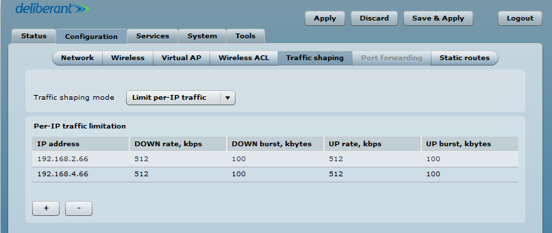
- IP address – specify the IP address for which the traffic will be limited.
- Down rate, kbps – specify the maximum download bandwidth value in Kbps.
- Down burst, kbytes – specify the download burst size in kbytes.
- UP rate, kbps – specify the maximum upload bandwidth value in Kbps.
- UP burst, kbytes – specify the download burst size in kbytes.
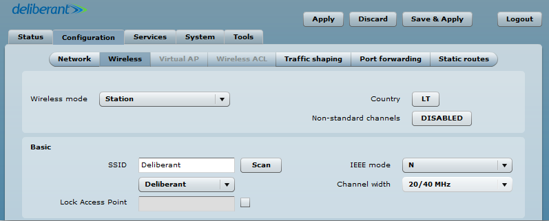
Set up CPE as a Router
Step 1. Navigate to Configuration > Wireless, set the Wireless mode to Station, and click Scan at the SSID field to choose the SSID of the AP that the station will be associated with. Then specify the [security parameters] for the AP, check the IEEE mode (these settings must match the AP’s wireless settings) and then click Save & Apply:
Step 2. Verify the connection. Navigate to Status > Information. The information page will present wireless information on the link with the access point. Connection status should display as Connected and progress bars indicating the quality of the connection should be present:
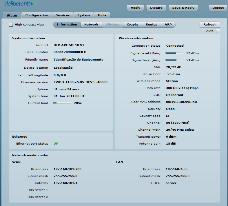
Step 3. Router Mode. This section allows users to customize the parameters of the Router to suit the needs of the network, including the ability to use the built-in DHCP server. When the device is configured to operate as a router, the following sections should be specified: WAN network settings, LAN network settings, and LAN DHCP settings.
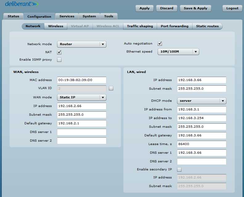
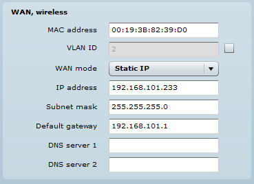
Step 4. WAN Settings. WAN network settings include options for the WAN interface. In this scenario, the WAN interface is on the wireless side. The access type of the WAN interface can be configured to be a Static IP, Dynamic IP, and PPPoE client.
WAN mode – choose Static IP to enter the IP settings for the device’s WAN interface:
Step 5. DHCP mode – choose server to enable the DHCP server on the LAN interface.
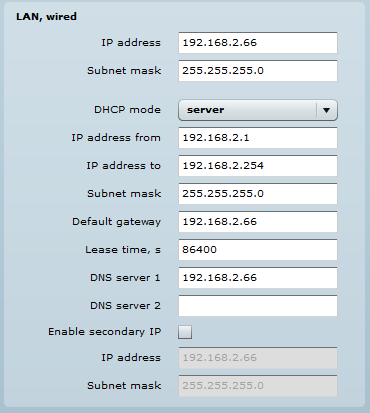
- IP address from – specify the starting IP address of the DHCP address pool.
- IP address to – specify the ending IP address of DHCP address pool.
- Subnet mask – specify the subnet mask.
- Default gateway – specify DHCP gateway IP address.
- Lease time – specify the expiration time in seconds for the IP address assigned by the DHCP server.
- DNS server – specify the DNS server IP address.
Example of DHCP Relay Configuration
What is the DHCP relay mode? The DHCP relay forwards DHCP messages between subnets with different sublayer broadcast domains.
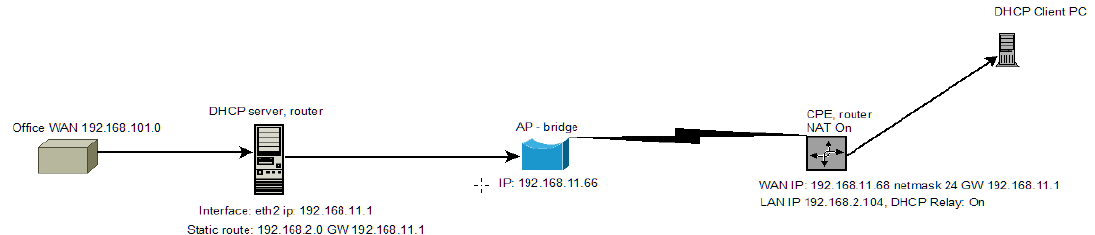
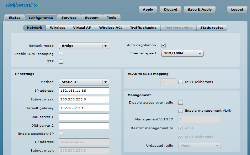
Step 1. Set the AP to function as a Bridge with IP 192.168.11.66 netmask 24, GW 192.168.11.1.
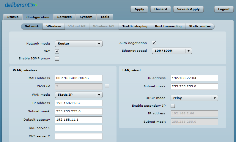
Step 2. Configure the CPE to function as a Router and connect it to an AP. Set the DHCP mode to Relay. Set the WAN mode to Static IP. The wireless IP address should be from the same subnet as the AP that allows users to reach the device wirelessly. A LAN wired IP address is used to reach the device from the LAN side and should be from the DHCP server’s subnet.
How to Test on Linux?
Step 1. Install the DHCP server on your Linux PC:
sudo apt-get install isc-dhcp-server
Step 2. Configure the DHCP server as follows:
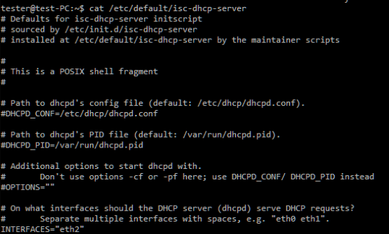
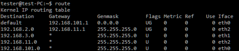
Step 3. Configure the DHCP server with an IP on the eth2 interface. IP on eth2: 192.168.11.1, netmask 24, GW 192.168.11.1.
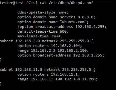
Step 4. Add a static route on the DHCP server to reach the x.2.0 LAN using the command sudo route add –net 192.168.2.0 netmask 255.255.255.0 gw 192.168.11.1.
Step 5. Test the configuration.
How to Configure the PPPoE Client?
In Router mode, the DLB APC will receive Internet access through the WAN port and will share it with the LAN ports that are separated with a different IP range. The type of connection to the WAN interface is determined by selecting Static IP, DHCP client, or PPPoE.
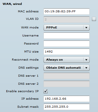
WAN mode – select PPPoE to set the WAN interface to connect to an ISP through a PPPoE. Add a username and password to the main configuration, while all other settings should be left as their default values:
Explanation of Parameters:
- MAC address – specify the clone MAC address, if required. The ISPs register the router’s MAC address and only allows that specific MAC address to connect to their network. In the case when there is a need to change the hardware (router), users must notify their ISPs about the change in the MAC address or they can simply set the router’s MAC address to the MAC address of the previously owned router/computer.
- VLAN ID – specify the VLAN ID for traffic tagging on the required radio interface [2-4095]. Station devices that associate using the particular SSID will be grouped into this VLAN.
- User name – specify the user name for the PPPoE.
- Password – specify the password for the PPPoE.
- MTU – specify the MTU (Maximum Transmission Unit). The default value is 1,500 bytes.
- Reconnect mode – set the PPPoE reconnection mode:
- Always on – the PPPoE connection will automatically start without a timeout. The router will keep trying to bring up the connection, if it is abruptly disconnected.
- On demand – the PPPoE connection will automatically start when there is outbound traffic to the Internet and it is automatically terminated, if the connection is idle, based on the value specified in the idle time [1-65535] settings.
- DNS settings – allows users to choose whether automatically assigned or alternative DNS servers are to be used.
- Enable IP alias – specify the alternative IP address and the netmask for APC unit management.