There are several solutions that users can implement, if a link is not working well.
1. Set the Channel width to the lowest available value.
2. Reduce Max data rate by half.
3. Set Transmit queue length to 8 (available on “Access Point iPoll” wireless mode only).
4. Set BA window size to 8 (available on “Access point (auto WDS) and “Station” wireless modes only).
The aforementioned changes can be performed in Configuration > Wireless.
If these solutions do not fix the problem, the problem may lie in the fact that the current channel has too many other Access Points (APs). To look for a better channel, navigate to Tools > Spectrum analyzer and click Start. Wait 20–30 seconds while the radio gathers enough packets to provide real time noise data.
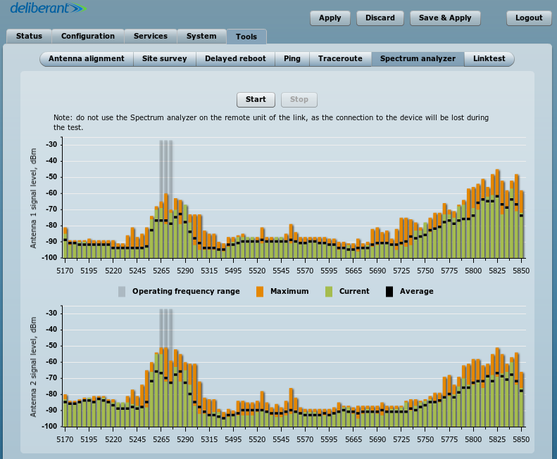
If the device’s operating channel is overcrowded, as shown by the high noise bars in the above picture, look for a frequency range where noise bars are the lowest. The above example shows that the frequency ranges with the least amount of noise are 5,170–5,230MHz and 5,490–5,725MHz.
To find the right channel and to avoid collision with other APs, perform a scan in Tools > Site survey.
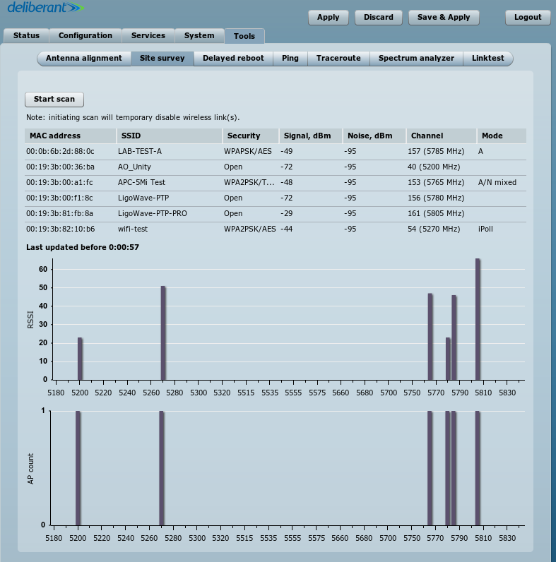
Choose a channel number that does not match the number indicated in the Channel column and which is within a clean frequency range. Then set it up on the AP (Configuration > Wireless).
Once the link is connected, test the ping times and speed. If the results are unsatisfactory, try another channel.
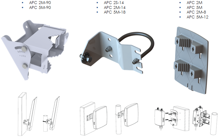
Outdoor Installation
There are three different types of mounting plates. All of them can be mounted on a wall or on a pole.
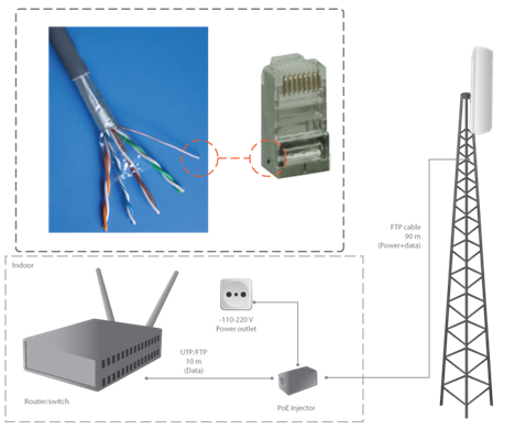
Cables
- length of cable connecting the switch and the APC device, <100m;
- use FTP cable outside;
- use shielded RJ45 plugs outside;
- it is recommended to solder the drain wire to the RJ45 plug;
- use UTP or FTP cable inside.
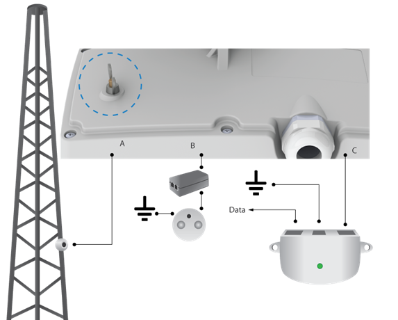
Grounding
Three options for grounding are available:
- Grounding stud on housing (only APC 5M-18/2M-14)
- Grounding with PoE adapter B
- Grounding with PoE inserter C
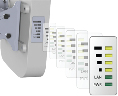
Alignment
Observe the signal level on the LED:
- both sides have to be aligned at the same time for the PTP link to be established;
- align the CPE on the multipoint network;
- standard RSSI thresholds are indicated by the top four LEDs.
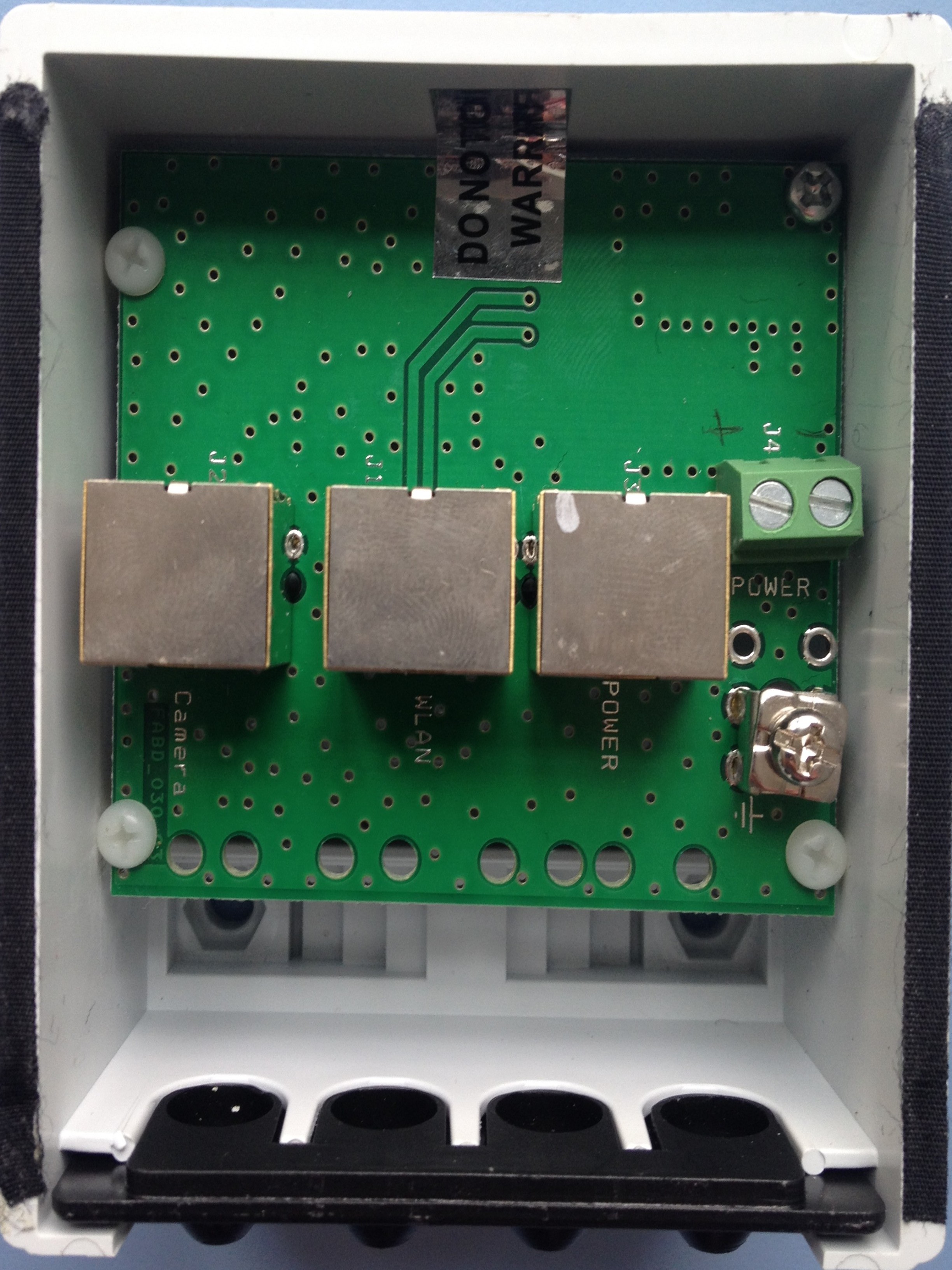
LigoWave’s PoE splitter is a passive outdoor device which provides PoE passthrough functionality for video surveillance and repeater setup scenarios. Besides powering two devices on the same tower through the PoE port or DC terminal block, it also has integrated ESD and surge protection circuits.
Step 1. Make sure that the power is not connected to a PoE splitter.
Step 2. Open the cover, feed the cables into the enclosure, and cut the wires, providing sufficient spare length. Connect the cables to the powered ports ETH1 and ETH2 (or Camera and WLAN).
Step 3. The splitter must be properly grounded to protect against lightning: the grounding wire must be attached and tightened with a bolt. Fix and fasten the power wires on the power port (polarity is important) or insert the Ethernet cable into the Power port (if power is supplied via Ethernet).
Step 4. Close the cover and verify the operation of all connected devices.
Datasheet: LigoPoE 分离器
Quick Installation Guide: PoE_分离器快速安装指南