在噪音环境中提升链路的稳定性和吞吐量
When a link does not work well, there are several options that you can try.
1. Set the Channel width to the lower available value. On LigoPTP 5 RapidFire there are available 5/10/20/40/80 MHz widths and on LigoPTP 4 RapidFire there are available 5/10/20 MHz widths.
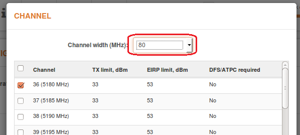
All above can be done in “Settings->Radio->Channel selection” tab on Master device.
If that does not help, probably current channel has too many other Access Points (APs).
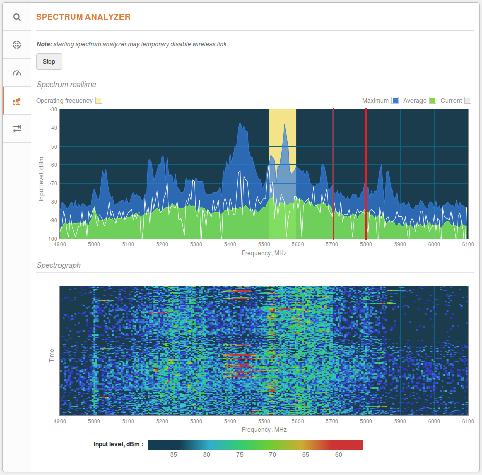
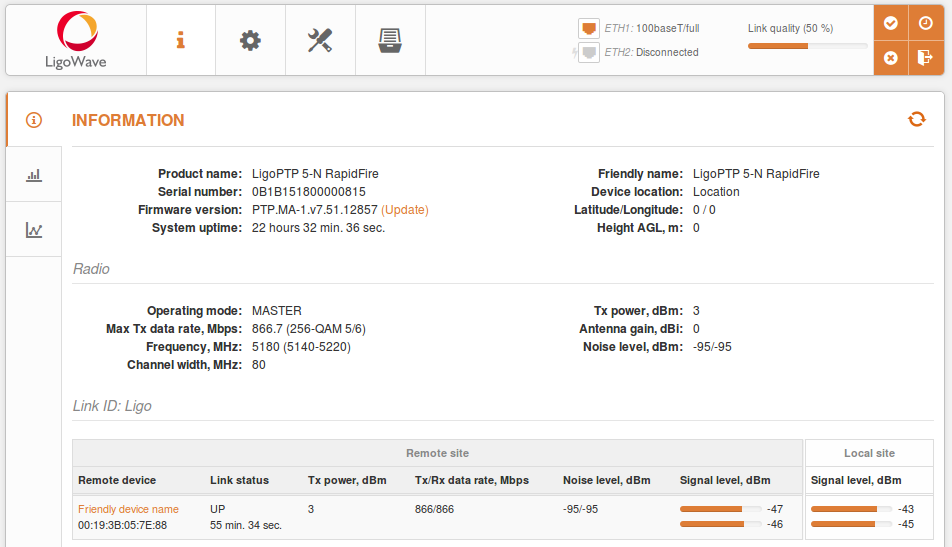
In order to look for a better channel, navigate to “Tools->Spectrum analyzer” tab. Click on “Start” button and wait at least 20-30 seconds while radio gathers enough packets to present real time noise.

If your current channel is on one of the highest noise bars, like in the picture above, look for a frequency range where noise bars are the smallest.
In this example, lower noise is in the range of 5300-5380 MHz and 5700-5780 MHz.
To find the right channel and avoid the collision with other APs, do the scan in “Tools->Site survey” tab.
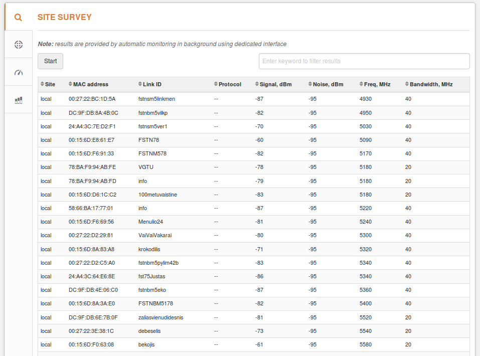
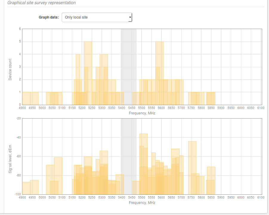
Choose a frequency, which does not match with the frequency at the Site Survey “Frequency” column, within the clear range and set it on the Master (Settings->Radio tab). Also try to avoid frequencies where you can see that other devices are working on adjacent frequencies. For example from the picture above you can see that 5430 MHz frequency does not have any devices working on it, however there are nearby devices which operates on 5500 MHz and 5300 MHz which might cause interference to your transmission especially the probability increases if there is a plan to use 80 MHz channel width.
Once the link is connected, use The Linktest speed tool to verify TX/RX data rate and the total capacity of the link. If the results aren’t good enough, try another channel or decrease channel width. If you noticed that speed is rather good, try to move current frequency by 5 MHz step, up or down and check if you can get higher throughput.
LigoPTP RapidFire的安装
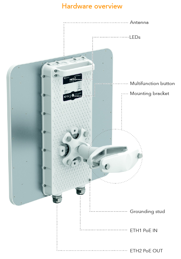
Installation
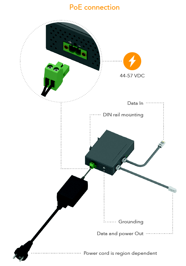
Recommended cables to use:
- Cable length from switch to LigoPTP device < 100 m
- Use FTP cable outside
- Use shielded RJ45 plugs outside
- It’s recommended to solder drain wire to RJ45 plug
- Use UTP or FTP cable inside
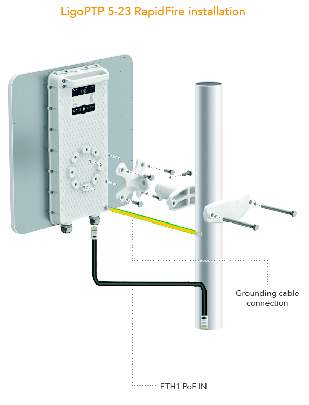
Proper grounding have to be made with stud on housing and with PoE inserter
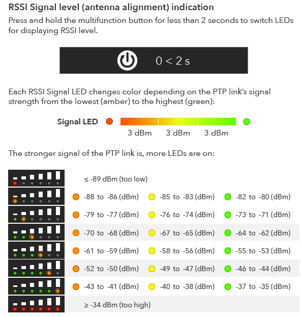
Alignment
To make correct antenna alignment there are multifunction LEDs for displaying RSSI level.
- Align both sides at once for PTP link
LigoPTP RapidFire LED灯说明
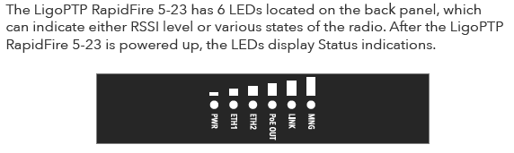
New model LEDs represent various devices operations: booting up, reset to default, reboot, firmware flashing, recovery mode a case of failure and main operation: device status and signal levels.
Signal level indication
Signal level change is represented in a a step of 1 dBm. For that we use 6 LEDs: LED1-6; three colors:
amber, yellow, green; and three levels of brightness: low, middle, high. When the signal is changing from low to high, LED1 starts
to lit in amber color from low to high brightness, then color changes to yellow, then color changes to green.
After that second LED2 starts from amber color low brightness and finishes in green color high brightness, etc.
Booting up
When device is booting up, each LED represents a phase of booting process. Starting from LED1 each LED turns on till all 6 LEDs are on. The GREEN color is for success operation.
If some booting/startup phase fails, that LED becomes RED. If any LED does turn on in RED that means failure.
LED1-3 are responsible for bootloader, LED4-6 are for kernel.
If all phases passes are OK, LEDs turn off and starts the main operation. If any of phase fails, LEDs remain to lit in that state till problem is solved.
Firmware upgrading / rebooting / resetting to defaults
During the firmware upgrade/reboot/reset blue LEDs starts to move as “snake”. The snake length is 6 LEDs and it goes from left to right and vice versa every 100 ms.
Recovery mode
If device goes to recovery mode (seldom case), all LEDs blink in red/yellow every half of second.
Operation on GUI
LEDs could be configured via GUI:
- Always off – LED indication will be always disabled
- Always on – LED indication will be always enabled
- Auto off – LED will be disabled at specified timeout
LigoPTP RapidFire复位按钮
Reset button
Reset button has 4 functions:
- Reset to defaults.
Press and hold reset button for 6 seconds till all LEDs are on and blinking. When reset button is pressed, every second LEDS from LED1 to LED6 starts to lit, after that all LEDs become to blink every half of second, which means that reset button can be released (for reset). - Wake up WiFi management radio
An activity of the WiFi management radio is time limited, therefore after some time the radio goes down. Press and hold reset button for 2-4 seconds till 2-4 LEDs are on to wake up the radio (works if the radio is not disabled from GUI) - Activate LEDs after timeout
Press for 1 second - Switch between LED main operating mode 1 and 2
Press for 1-2 seconds to turn LEDs to signal indication (mode 1) and back to device state indication (mode 2)
如何进行天线校准
The Antenna Alignment tool measures signal quality between the Master and Slave. For best results during the antenna alignment test, turn off all wireless networking devices within range of the device except the device(s) with which you are trying to align the antenna. Watch the constantly updated display as you adjust the antenna.
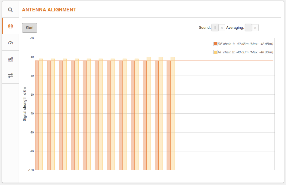
Start/Stop – press this button to start or to stop antenna alignment.
Averaging – if this option enabled, the graph will display the average Signal Strength of both vertical and horizontal polarizations.
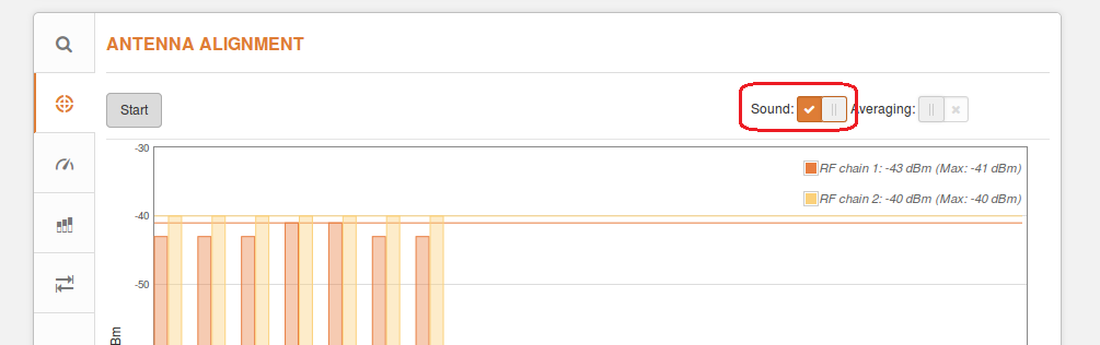
Sound – with this option enabled, the sound (beeps) will be produced during the aligning process, if browser allows this.
How to properly align antennas
1. Disable ATPC functionality;
2. Set max tx power;
3. Choose Compliance testing country code during installation.
After alignment will be finished choose your country code and enable ATPC functionality.
LigoPTP RapidFire devices could be mounted on the pole. Minimum and Maximum pole diameter sizes are given bellow:
| Product | Compatible pole diameters, cm | |
| Min, cm | Max, cm | |
| LigoPTP RapidFire | 3 | 11 |